

2 layers33 × 90 mm

 emard/esp32blesynscan2
ESP32 Arduino BLE UART bridge for SynScan Pro attempt
Blesyn is an open-source printed circuit board by emard, from the emard/esp32blesynscan repository on GitHub. It is a 2-layer board of 17.8 × 35.6 mm with 11 parts on 17 nets, routed with 43 tracks and 0 vias.
It is built around the R-783.3-0.5 and BAT42. Its parts include 4 resistors, 4 diodes, 2 ICs and 1 connector. It belongs with the radio and wireless and interfaces and adapters boards and the ESP32 boards of this library.
Micropython ESP32, ESP32S3, ESP32C3 Bluetooth Low Energy (BLE) Motor server, WiFi Motor Server and USB-WiFi Motor Client for SynScan Pro on Windows, Linux, Android. Arduino ESP32 Bluetooth Classic UART bridge for SynScan Pro under Wine on Linux. UART 3.3V TTL is connected to SkyWatcher Virtuoso Mini or Virtuoso GTi mount.
ESP32C3 USB-C port can be used as direct USB-SERIAL on PC connected to Motor over wire or remote USB-SERIAL over WiFi.
Do not use this to upgrade Motor firmware. Motor firmware should be upgraded over wire using USB-SERIAL UART 3.3V TTL based on PL2303 or FT232R chip.
"micropython" directory contains latest developent. To install, continue with micropython/README.md
"Arduino" directory contains old code which should be upgraded with features micropython code has. To install, continue with Arduino/README.md
Bluetooth Classic is available only for Arduino. Micropython doesn't support Bluetooth Classic.
There should be 12V->3.3V converter. To save power recommended is switching converter (Canton Power or RECOM). RJ-12 plug can't guarantee that GND makes connection before 12V pin. Hot-plugging can apply 12V to 3.3V pins and risk a permanent damage. Avoid hot-plugging.
On the mount "Virtuoso Mini" RX and TX are labeled swapped and seems as wired together making it a half-duplex serial port and ESP32 should cancel echo. ESP32 TX line should "simulate" open collector output with a resistor 10k and small low drop diode BAT42.
On the mount "Virtuoso GTi" RX and TX are labeled normal and are not wired together making it a full-duplex serial port without echo. ESP32 TX line should connect directly to ESP32.
In the mount manual see RJ-12 pinout. Conenct RJ-12 RX/TX with short straight RJ-12 cable to ESP32 RX2/TX2 pins.
First prototype (ESP32)
             Canton Power
            ┌─────────────┐
            │IN        OUT│
            │12V  GND 3.3V│
            └─────────────┘
              │    │    │
  MOUNT       │    │    └───────────────┐
 MINI/GTi     │    │                    │   ESP32
┌───────┐     │    │                    │  ┌───────┐
│    12V│─────┘    │         10k/BAT42  └──│3.3V   │
│       │          │         ┌─░░░░─┐      │       │
│     TX│──────────│─────────┼──>∫──┴──────│TXD    │
│       │          │         └─────────────│TX     │
│     RX│──────────│───────────────────────│RX     │
│       │          │                       │       │
│    GND│──────────┴───────────────────────│GND    │
└───────┘                                  └───────┘
Minimal schematic (ESP32S3) old
                 RECOM
             R-78K3.3-0.5
            ┌─────────────┐
            │12V  GND 3.3V│
            │IN        OUT│
            └─────────────┘
              │    │    │
  MOUNT       │    │    └─────────┐
 MINI/GTi     │    │              │   ESP32S3
┌───────┐     │    │              │  ┌───────┐
│    12V│─────┘    │   10k/BAT42  └──│3.3V   │
│       │          │    ┌─░░░░─┐     │       │
│     TX│──────────│────┼──>∫──┴─────│TXD    │
│       │          │    └────────────│TX     │
│     RX│──────────│─────────────────│RX     │
│       │          │                 │       │
│    GND│──────────┴─────────────────│GND    │
└───────┘                            └───────┘
Minimal schematic (ESP32S3) new
                 RECOM
             R-78K3.3-0.5
            ┌─────────────┐
            │12V  GND 3.3V│
            │IN        OUT│
            └─────────────┘
              │    │    │
  MOUNT       │    │    └─────────┐
 MINI/GTi     │    │              │   ESP32S3
┌───────┐     │    │   10k/BAT42  │  ┌───────┐
│    12V│─────┘    │    ┌─░░░░─┐  └──│3.3V   │
│       │          │    ├──>∫──┴─────│TXD    │
│     TX│──────────│────┴────────────│TX     │
│       │          │    ┌─░░░░─┐     │       │
│     RX│──────────│────┼──>∫──┴─────│RXD    │
│       │          │    └────────────│RX     │
│    GND│──────────┴─────────────────│GND    │
└───────┘                            └───────┘
part numbers and pinouts
RJ-11 or RJ-12 Connector
Mouser P/N: 538-95501-2661   0.5$
Mouser P/N: 523-RJE031660310 1$
Mouser P/N: 490-CRJ051-1-TH  2$

  RJ-12         RJ-11
┌────────┐    ┌────────┐
│ 123456 │    │  2345  │
│        │    │        │
└──┐  ┌──┘    └──┐  ┌──┘
   └──┘          └──┘
front view    front view

1        N.C.
2 yellow TX       (3.3V) (esp32 sends to "Mini", receives from "GTi")
3 green  Vpp+     ( 12V) (esp32 draws power)
4 red    RX       (3.3V) (esp32 receives from "Mini", sends to "GTi")
5 black  GND
6        N.N.

Voltage converter 4.5-36V -> 3.3V
Mouser P/N: 919-R-78K3.3-0.5 7$

RECOM Looking at female RJ-12 socket on the mount:
┌────────┐
│ 123456 │
│        │
└──┐  ┌──┘
   └──┘

1 blue   N.C.
2 yellow TX       (3.3V) (mount "Mini" receives, "GTi" sends)
3 green  Vpp+     ( 12V) (mount provides power)
4 red    RX       (3.3V) (mount "Mini" sends, "GTi" receives)
5 black  GND
6 white  Reserved (3.3V)
RX/TX roles on the mount "Virtuoso Mini" are swapped and actually indicate RX2/TX2 on ESP32.
Virtuoso Mini  ESP32
-------------  ----------
2 yellow TX    TX2 GPIO17 (over resistor/diode)
4 red    RX    RX2 GPIO16
5 black  GND   GND
RX/TX roles on the mount "Virtuoso GTi" are labeled normal, here we swap TX2/RX2 on ESP32.
Virtuoso GTi   ESP32
------------   ----------
2 yellow TX    RX2 GPIO17 (direct)
4 red    RX    TX2 GPIO16
5 black  GND   GND
RJ-11 4-pin socket can be used instead of RJ-12 6-pin because pins 1 and 6 are not connected.
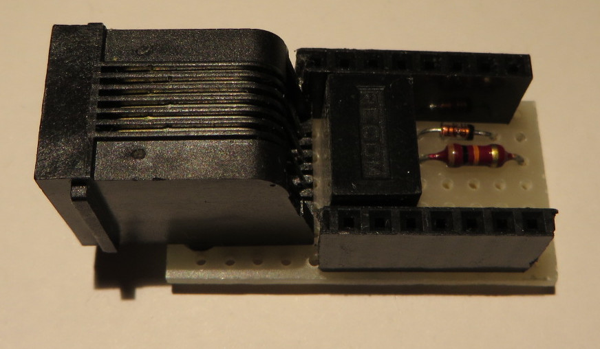
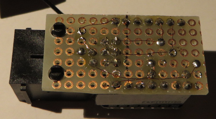
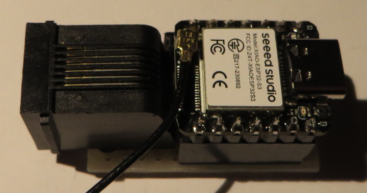
RJ12 pinout on the adapter matches the pinout on the mount, so the "straight" wired cable should be used.
There are different RJ-11 and RJ-12 cables, with straight and cross wiring. For the telephones it does not matter but here it matters!
STANDARD PHONE CROSS CABLE MAY NOT BE SUITABLE. USE ONLY STRAIGHT WIRED 4-PIN RJ-11 or STRAIGHT WIRED 6-PIN RJ-12. CROSS RJ-11 AND RJ-12 CABLES AND ALL 2-PIN RJ-11 CABLES ARE NOT SUITABLE. IF A CROSS WIRED CABLE OR ANY 2-PIN CABLE IS CONNECTED THEN 12V WILL FRY ELECTRONICS IN THE MOUNT AND ESP32.
After board power ON or reset by pressing "EN" button, blue LED will turn ON for 1.5 seconds.
By default if nothing is pressed ESP32 provides Bluetooth Low Energy Serial.
If "BOOT" button is held during blue LED is ON then ESP32 will provide Bluetooth Classic Serial.
ESP32 in Bluetooth Low Energy mode only supports BLE protocol and does not save battery power. In both Classic and Low Energy modes ESP32 consumes about 70 mA.
Synscan works in BLE mode.
SynScan pro -> Settings -> Connection Settings -> BLE
If device no longer appears in connect list and you want to retry connecting, then android application has to be stopped and started again:
View applications as smaller windows. To stop SynScan, drag it left on ardoid 10 or drag it up on android 14.
Protocol testing:
"Serial Bluetooth Terminal" can connect in Bluetooth Classic directly when ESP32 is booted in Bluetooth Classic mode.
"Serial Bluetooth Terminal" can connect in Low Energy mode with long touch on SynScan_BLE device selecting "Edit" Custom profile and then accepting offered UUID values for Service, Read and Write. Settings:
Receive Newline = CR
Send    Newline = Auto (Same as Receive)
Send    Local Echo ( o) enabled
Basic request/response works:
request
:e1\r

response
=0210A1\rBluetooth classic works from linux and SynScan 2.5.2 pro running under wine, connecting as serial port.
in shell 1
hcitool scan
Scanning ...
        24:0A:C4:11:22:33   SynScan_BT
rfcomm bind /dev/rfcomm0 24:0A:C4:11:22:33
unzip synscanpro_windows_252.zip
cd SynScanPro
wine SynScanPro.exe
... wine will initialize com1 as symlink to /dev/ttyS0
... we must change this symlink to /dev/rfcomm0
in shell 2
cd ~/.wine/dosdevices
ln -sf /dev/rfcomm0 com1
in SynScan Pro window
... SynScan pro -> Settings -> Connect Settings -> Serial
... Serial Port: COM1
... press top "<" touch btn then "Connect" btn will appear.
... touch "Connect" btn, retry few times
SynScanPro can be debugged from wine:
winedbg --gdb SynScanPro.exe
...
Wine-gdb> cBluetooth low energy works from linux and SynScan 2.5.2 pro running under wine, connecting as serial port.
It works over ble-serial if esp32 is emulating BLE nRF chip. RN4871 chip emulation will not be detected by ble-serial.
Install
https://github.com/Jakeler/ble-serialin shell 1
source ble-venv/bin/activate
ble-scan -i hci1
        24:0A:C4:11:22:33   SynScan_BLE
ble-serial -i hci1 -d 24:0A:C4:11:22:33
(ble-venv) guest@nuc1:~$ ble-serial -i hci1 -d 24:0A:C4:11:22:33
23:38:03.521 | INFO | linux_pty.py: Port endpoint created on /tmp/ttyBLE -> /dev/pts/2
23:38:03.521 | INFO | ble_interface.py: Receiver set up
23:38:03.741 | INFO | ble_interface.py: Trying to connect with 24:0A:C4:11:22:33: SynScan_BLE
23:38:05.443 | INFO | ble_interface.py: Device 24:0A:C4:11:22:33 connected
23:38:05.443 | INFO | ble_interface.py: Found write characteristic 6e400002-b5a3-f393-e0a9-e50e24dcca9e (H. 44)
23:38:05.443 | INFO | ble_interface.py: Found notify characteristic 6e400003-b5a3-f393-e0a9-e50e24dcca9e (H. 41)
23:38:05.826 | INFO | main.py: Running main loop!
in shell 2
cd SynScanPro
wine SynScanPro.exe
... wine will initialize com1 as symlink to /dev/ttyS0
... we must change this symlink to /dev/rfcomm0
in shell 3
cd ~/.wine/dosdevices
ln -sf /tmp/ttyBLE com1
in SynScan Pro window
... SynScan pro -> Settings -> Connect Settings -> Serial
... Serial Port: COM1
... press top "<" touch btn then "Connect" btn will appear.
... touch "Connect" btn, retry few times
SynScanPro can be debugged from wine:
winedbg --gdb SynScanPro.exe
...
Wine-gdb> cWith suitable BLE adapter, for example TP-LINK UB500 SynScan pro 2.5.2 for windows connects with "SynScan_BLE".
"SimplySerial" is simple terminal emulator for windows. It can can be started from powershell to print debug messages from esp32.
./ss -com:8 -baud:9600
Connected
DisconnectedESP32 creates a bluetooth server with serial port bridge. Phyisical TTL serial port should be 9600,8,n,1. Using 9800 baud seems to receive less noise than 9600 baud.
Minimum that works is a BLE Service (UUID 0xA002) with two characteristics, one for RX other for TX:
RX Direction SynScan->motor (UUID 0xC302)
Bluetooth LE packetizes serial protocol so entire message is delivered in one packet. ESP32 filters out some problematic commands for "2.16.A1" motor firmware (see Firmware bugfix) other firmwares may not need it. Message is written to TTL serial and signaled with "NOTIFY" flow control.
TX Direction motor->SynScan (UUID 0xC306)
TTL serial receiver buffers bytes until "complete" message is received, it begins with '=' or '!' and ends with '\r'. It is delivered via bluetooth and signaled with "INDICATE" flow control.
Mount's serial TTL port is half-duplex and it seems that mount has hardware loopback. So everything that esp32 sends to the mount, the mount immediately echoes it.
In the code there is echo cancellation built in to reduce BLE traffic, run faster and save energy.
Mount and ESP32 cannot send at the same time. If ESP32 tries to send while mount sends, then the data received by ESP32 will be just noise.
Received bytes are occasionaly wrong with typically one of the bits that should be 0 errorenously received as 1. This happens less often when mount is just powered one and more often after alignment when mount is driving motors for tracking.
Motor firmware version 2.16.A1 is the latest but has problem with SynScan application on android. After each connect user must enable "Auxiliary Encoder" otherwise mount will start turning around azimuth axis and will never stop by itself (user should press cancel to stop).
According to BDN at Cloudy Nights this bug can be fixed by making USB-SERIAL adapter and flashing firmware MC006_Tracking_V0216.MCF posted by Antoine1997 at Stargazer's Lounge.
Although this firmware also has version 2.16.A1 it is different and fixes the encoders problem. Warning flashing firmware using WiFi dongle will brick the board and should never be tried, so use only usb-serial.
If you are not comfortable with flashing the firmware, here is the fix that forces using Auxiliary encoders.
fix#1: in function "udpcb()" one message is rewritten with this fix Auxiliary Encoder doesn't have to be enabled. It seems that mount internally always uses Auxiliary Encoders. Regardless of Auxiliary Encoders being set ON or OFF without this patch, when clutches are released and mount is manually moved, SynScan always knows its new position.
:W2050000\r -> :W2040000\rfix#2: prevents sending junk to motor firmware which is easy to crash.
SynScan sends some AT command probably for its original SynScan WiFi ESP8266 AT firmware. This AT command should not reach motor firmware so "udpcb()" function rewrites this AT command as ":e1\r" and to this command motor firmware responds with version number which is not really response to AT command but SynScan accepts it.
AT+CWMODE_CUR?\r\n -> :e1\rfix#3: receive buffer is discarded after timeout of 10 ms or when unexpected (noise) byte is received outside of expected chars "=0123456789ABCDEF!\r". Synscan will retry the command after its own timeout. This fix improves initial connect, without this fix and without open collector fit with diode and resistor, SynScan sometimes needs to be manually restarted few times to connect.
| Qty | Value | Footprint | References |
|---|---|---|---|
| 2 | 10k | Resistor_SMD:R_1206_3216Metric_Pad1.30x1.75mm_HandSolder | R3, R4 |
| 2 | 10k | Resistor_THT:R_Axial_DIN0207_L6.3mm_D2.5mm_P10.16mm_Horizontal | R1, R2 |
| 2 | BAT42 | Diode_SMD:D_1206_3216Metric_Pad1.42x1.75mm_HandSolder | D3, D4 |
| 2 | BAT42 | Diode_THT:D_DO-34_SOD68_P7.62mm_Horizontal | D1, D2 |
| 1 | R-783.3-0.5 | Converter_DCDC:Converter_DCDC_RECOM_R-78E-0.5_THT | U2 |
| 1 | RJ12 | Connector_RJ:RJ12_Amphenol_54601-x06_Horizontal | J1 |
| 1 | XIAO-ESP32-S3 | xiao:XIAO-ESP32-S3-DIP | U1 |
It measures 17.8 × 35.6 mm and has 2 copper layers, 1.6 mm thick.
11 parts, built around the R-783.3-0.5 and BAT42. The full list of its parts is on this page, with links to each part's symbol and footprint where PCBKit's library has them.
From the emard/esp32blesynscan repository on GitHub, at the commit this page was made from: the board is pcb/blesyn/blesyn.kicad_pcb and its schematic pcb/blesyn/blesyn.kicad_sch. PCBKit opens the board in the browser, with nothing to install.
Its repository states no licence, so its author keeps all rights: ask emard before reusing the design.


Mickael235/pic16-biometric-access-control
Biometric access-control system based on PIC16F88, SFM3050-TC1 fingerprint sensing, RS232 communication, relay control, KiCad PCB design and SolidWorks enclosure.

wipmate/electronics
A collection of small ESP32-powered PCBs for use in smart home appliances.
