


2 layers20.3 × 31.5 mm
HackaBLE
electronut/ElectronutLabs-hackaBLE
A tiny Nordic nRF52832 based board you can embed in your BLE projects.
33 parts43
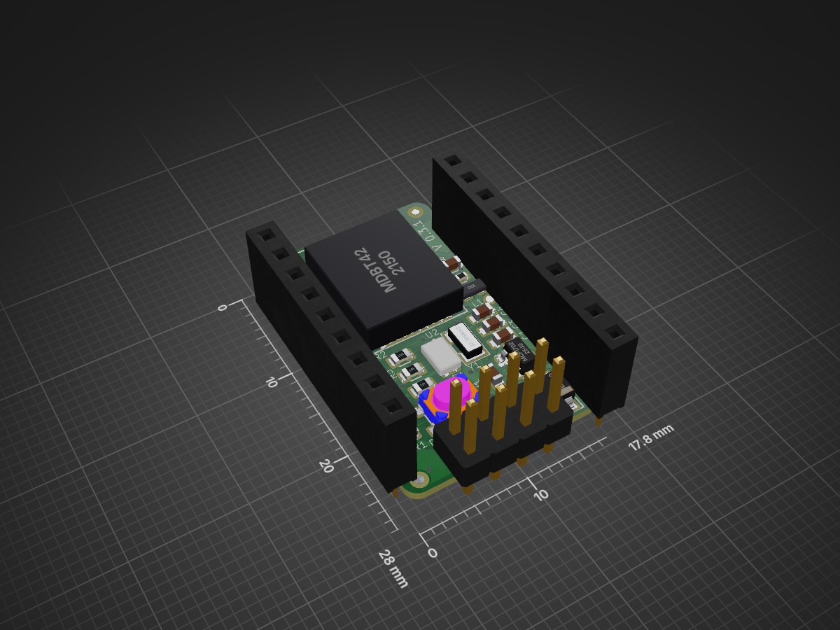
A tiny Nordic nRF52832 based board you can embed in your BLE projects.
HackaBLE is an open-source printed circuit board by electronut, from the electronut/ElectronutLabs-hackaBLE repository on GitHub. It is a 2-layer board of 17.8 × 28 mm with 33 parts on 44 nets, routed with 382 tracks and 48 vias.
It is built around the MDBT42Q and MBR130. Its parts include 9 connectors, 8 capacitors, 4 resistors, 2 ICs and 2 diodes. It belongs with the radio and wireless boards and the nRF52 and nRF5x boards of this library.
Note: This repository has been moved to our GitLab page on May 2019, and will not receive any updates or be monitored. Please follow this link to go to the new repository: https://gitlab.com/electronutlabs-public/ElectronutLabs-HackaBLE
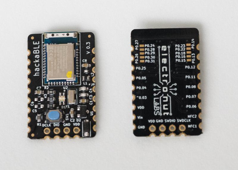
hackaBLE is a tiny (~ 18 mm x 28 mm) Open Source Nordic nRF52832 based BLE development board you can embed in your BLE projects. It's designed such that you can use it in three ways:
hackaBLE uses offers more value than just using the BLE module directly - since it incorporates the necessary passive components - including the ones for the buck converter for power saving - and adds an RGB LED and a button for convenience. It's also much easier to solder than the bare modules.
Features
Currently, there are two versions available in the market. Select your version of hackaBLE from below and follow the documentation.
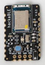
This is the latest version of hackaBLE it uses Raytac's nRF52832 module by Nordic Semiconductors. This version uses MCP1702, a 3.3 V voltage and protection diode at the input which enables hackaBLE to consume very low current and also provides reverse current protection. It also comes with an RGB LED, user reset button and SWD programming headers.
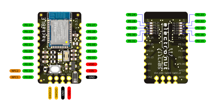
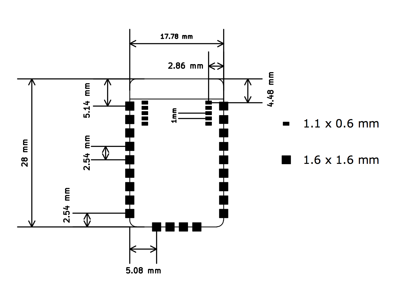
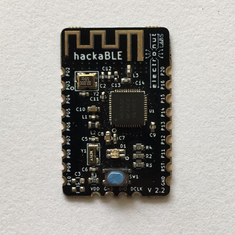
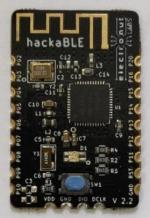
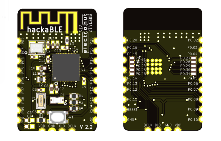
hackaBLE v2.2 is a redesigned hackaBLE that used the BLE SoC directly rather than a module. This version of hackaBLE also comes with an RGB LED, button, and SWD programming headers. It has onboard BLE antenna.
[CAUTION] hackaBLE v2.2 does not come with a regulator since it's designed for low power applications. MAX input to VDD is 3.6 V.
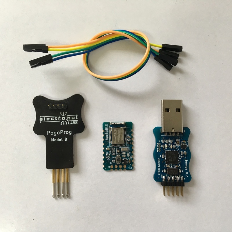
hackaBLE uses the Nordic nRF52832 which in turn is based on an ARM Cortex-M4 core. So you can really program it with any ARM compatible programmer. We do have a convenient solution though, in the form of our Bumpy Blackmagic probe compatible SWD debugger and our PogoProg.
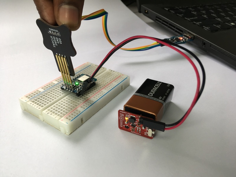
As shown above, use the four SWD pins of PogoProg on hackaBLE to upload or debug hackaBLE.
Please read the bumpy documentation on using Bumpy to program hackaBLE.
For more details on nRF52 programming, please read our guide on getting started with Nordic nRF5 SDK.
hackable does not ship with a bootloader, but it is supported in Arduino. Please visit here for details (but select Hackable in the board's menu).
Here's a blog article which will help you create a BLE custom characteristic and program it to hackaBLE using Arduino IDE.
For more detailed programming guide go here
hackaBLE can be used on a breadboard. Here's a video that shows how to solder headers on to hackaBLE.

hackaBLE is available for purchase from our Tindie store. Please email us at info@electronut.in if you have any questions.
You can find all code and design files related to HackaBLE in this repository.
Electronut Labs is an Embedded Systems company based in Bangalore, India. More information at our website.
| Qty | Value | Footprint | References |
|---|---|---|---|
| 3 | 1uF | Capacitors_SMD:C_0603 | C1, C2, C8 |
| 2 | 100R | Resistors_SMD:R_0603 | R3, R4 |
| 2 | 12pF | Capacitors_SMD:C_0603 | C3, C4 |
| 2 | 300pF | Capacitors_SMD:C_0603 | C5, C6 |
| 2 | GPIO | hackaBLE:Pin_Header_Straight_1x07_Pitch2.54 | J4, J6 |
| 2 | GPIO | hackaBLE:5pin_header | J5, J7 |
| 2 | SWD | hackaBLE:Pin_Header_Straight_1x04_Pitch2.54 | J3, J8 |
| 1 | 10K | Resistors_SMD:R_0603 | R1 |
| 1 | 10uF | Capacitors_SMD:C_0603 | C7 |
| 1 | 10uH | Inductors_NEOSID:Neosid_Inductor_SM0603CG | L1 |
| 1 | 15nH | Inductors_SMD:L_0402 | L2 |
| 1 | 200R | Resistors_SMD:R_0603 | R2 |
| 1 | 32.768KHz | hackaBLE:ABS07_crystal | Y1 |
| 1 | INPUT | hackaBLE:Pin_Header_Straight_1x02_Pitch2.54 | J1 |
| 1 | LED_ARGB | hackaBLE:RGB_LED | D1 |
| 1 | LOGO | hackaBLE:EL_logo | G*** |
| 1 | MBR130 | Diodes_SMD:D_SOD-123 | D2 |
| 1 | MCP1702 | TO_SOT_Packages_SMD:SOT-23 | U1 |
| 1 | MDBT42 | hackaBLE:MDBT42 | U2 |
| 1 | NFC | hackaBLE:Pin_Header_Straight_1x02_Pitch2.54 | J2 |
| 1 | SW_Push | hackaBLE:PTS810_Switch | SW1 |
| 1 | TEST_1P | hackaBLE:test_point | J9 |
The 30 most common of 33 parts.
It measures 17.8 × 28 mm and has 2 copper layers, 0.8 mm thick.
33 parts, built around the MDBT42Q and MBR130. The full list of its parts is on this page, with links to each part's symbol and footprint where PCBKit's library has them.
From the electronut/ElectronutLabs-hackaBLE repository on GitHub, at the commit this page was made from: the board is pcb/ver0.3/hackaBLE.kicad_pcb. PCBKit opens the board in the browser, with nothing to install.
Its repository states no licence, so its author keeps all rights: ask electronut before reusing the design.

IoTReady/low-power-nrf52-weighing-scale
https://iotready.co/low-power-nrf52-weighing-scale/


sckim/KiCAD
휘트스톤 브리지(Wheatstone Bridge)는 저항 4개로 두 개의 분압기를 만들고, 두 중간점의 전압 차이로 저항의 균형 여부를 판단하는 회로이다. 이 예제에서는 예제 1의 흐름(회로도 → PCB)에 더해 KiCad에 내장된 SPICE 시뮬레이터(ngspice) 로 회로를 먼저 계산해 보는 방법을 익힌다.

shraken/mdbt42q_bobby
A MDBT42Q break-out board for Nordic nRF52832 chip family

Appiko/sense_snap_hw
This repository contains all the KiCad based PCB design and related documentation for all the PCBs developed at Appiko.

