

2 layers
Controls
VladimirVladimirovMinkov/UOA_HPA
This is a code and document repository for the University of auckland Aeronaughtics Club Human Powered Aircraft
16 parts1

 EldinLz/esp32-sensor-daq
Custom ESP32-C3 sensor data acquisition PCB, firmware, fabrication files, and validation plan.
ESP32 Sensor Data Acquisition Board is an open-source printed circuit board by EldinLz, from the EldinLz/esp32-sensor-daq repository on GitHub. It is a 2-layer board of 73.5 × 65.5 mm with 16 parts on 23 nets, routed with 109 tracks and 0 vias.
It is built around the ESP32-C3-DEVKITM-1 and BME280. Its parts include 5 resistors, 2 ICs, 1 capacitor, 1 diode and 1 connector. It belongs with the sensors and measurement boards and the ESP32 and RISC-V boards of this library.
A custom two-layer PCB and Arduino firmware project for collecting ambient-light, temperature, humidity, and pressure data with an ESP32-C3.
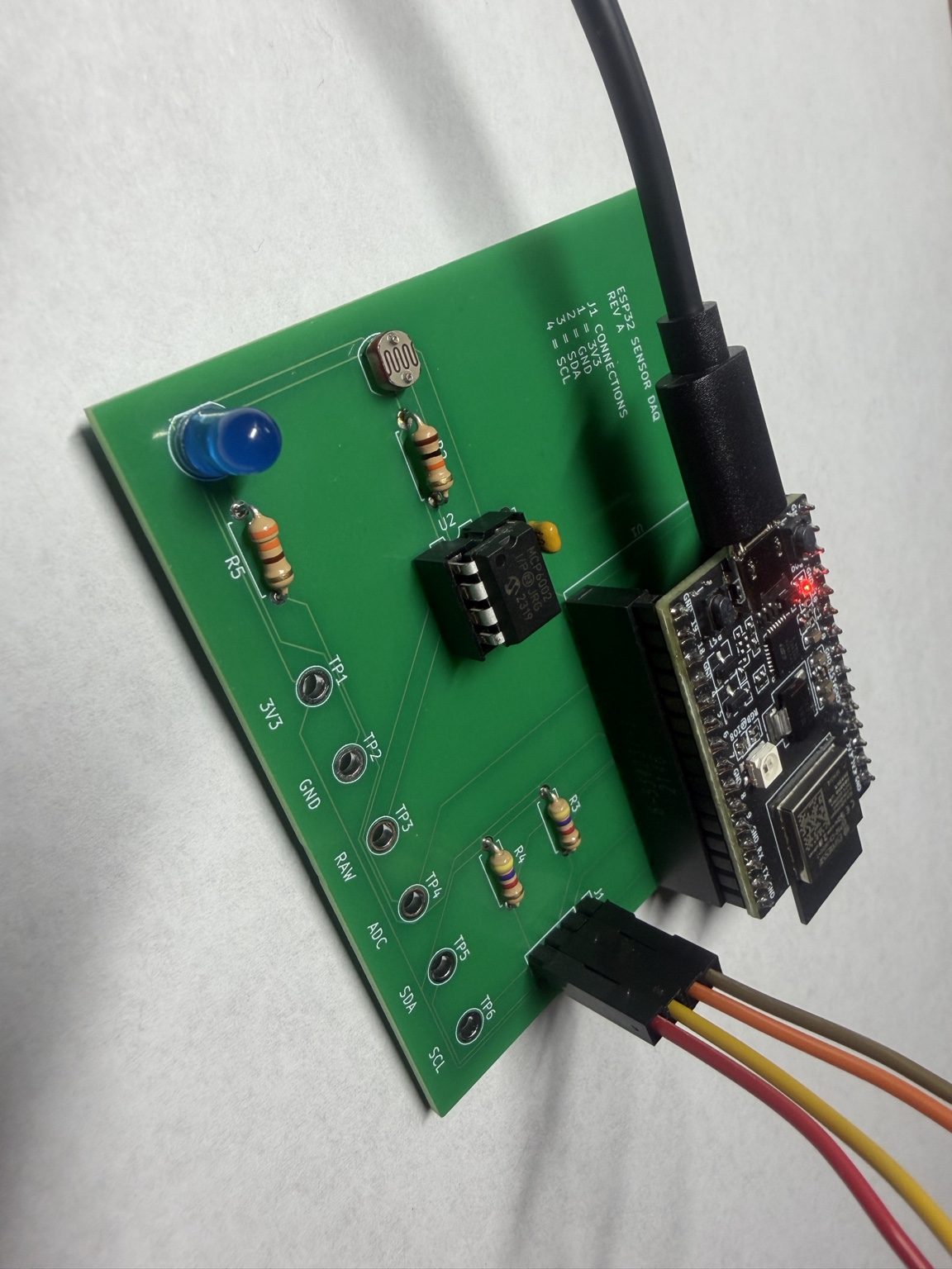
Project status: Rev A was hand-assembled, programmed, and hardware-validated on 2026-08-22. The ESP32-C3 streams serial CSV data, the BME280 is detected over I2C, and the MCP6002-buffered light channel responds from covered to bright-light conditions. Long-duration logging and calibrated light measurement have not been completed.
This project combines a custom KiCad carrier board with an ESP32-C3 DevKitM-1. A photoresistor signal is conditioned by an MCP6002 op-amp and sampled by the ESP32 ADC, while a BME280 breakout provides environmental data over I2C. Six labeled test points expose the primary power and signal nets for structured bring-up and debugging.
flowchart LR
    LDR["Photoresistor divider"] --> OP["MCP6002 buffer"]
    OP --> ADC["ESP32-C3 GPIO0 / ADC"]
    BME["BME280 temperature, humidity, pressure"] -->|"I2C: GPIO4 SDA, GPIO5 SCL"| ESP["ESP32-C3"]
    ADC --> ESP
    ESP --> LED["Status LED on GPIO7"]
ESP --> USB["CSV data over USB serial"]The Rev A PCB was assembled by hand with the ESP32-C3 in removable socket headers and the BME280 connected through the labeled J1 I2C header.
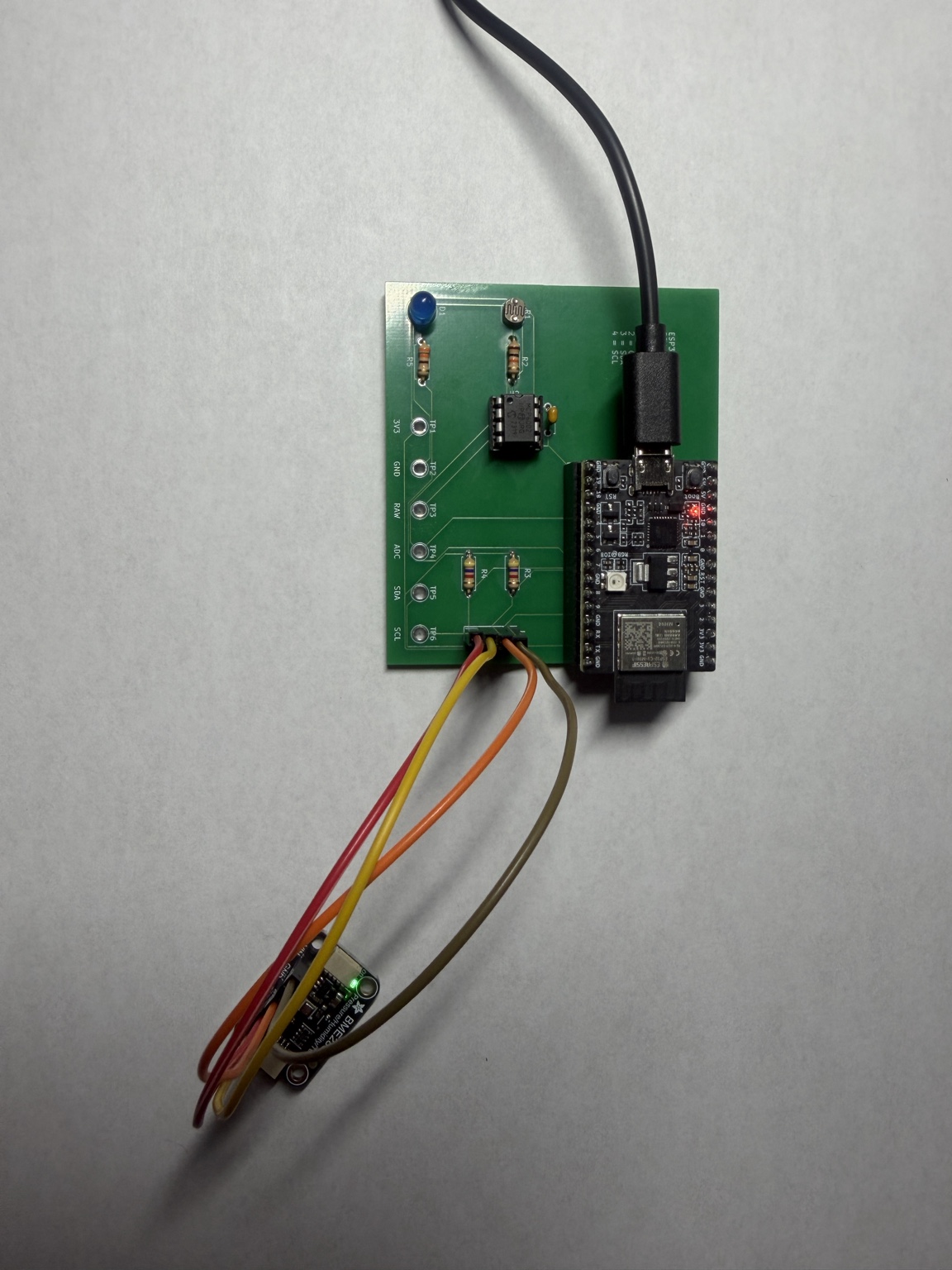
| Function | ESP32-C3 pin | PCB test point or connector |
|---|---|---|
| Light sensor ADC | GPIO0 | TP4 ADC |
| I2C SDA | GPIO4 | TP5 SDA, J1 pin 3 |
| I2C SCL | GPIO5 | TP6 SCL, J1 pin 4 |
| Status LED | GPIO7 | D1 through R5 |
| 3.3 V | 3V3 | TP1, J1 pin 1 |
| Ground | GND | TP2, J1 pin 2 |
| Raw light-divider signal | - | TP3 RAW |
The Arduino firmware:
0x77, then tries 0x76 as a fallback.Measured Rev A serial output:
BME280 detected
time_ms,light_raw,light_percent,temperature_C,humidity_percent,pressure_hPa
628,2058,50.3,25.70,47.22,1009.73esp32 board package by Espressif Systems 3.3.11ESP32C3 Dev ModuleThese captured values demonstrate end-to-end operation; they are not calibration data.
| Check | Result | Captured evidence |
|---|---|---|
| Post-assembly power-off check | Pass | No 3V3-to-GND short was found. |
| 3.3 V operation | Pass | The assembled board powered and ran from the ESP32-C3 3.3 V rail. |
| Firmware and serial output | Pass | Firmware uploaded successfully and produced one 115200-baud CSV row per second. |
| BME280 I2C sensing | Pass | Serial Monitor reported BME280 detected; observed readings were about 25.2-26.0 C, 47-49% RH, and 1009.7-1009.9 hPa. |
| Light channel - covered | Pass | light_raw approximately 247-265; light_percent approximately 6.0-6.5%. |
| Light channel - room light | Pass | light_raw approximately 1887-2134; light_percent approximately 46.1-52.1%. |
| Light channel - flashlight | Pass | light_raw = 4095; light_percent = 100.0%. |
| Status LED | Pass | A brief firmware-driven activity blink was observed. |
light_percent is the 12-bit ADC reading normalized to full scale; it is not a calibrated lux measurement. The light tests validate the complete photoresistor-divider, MCP6002-buffer, ADC, firmware, and serial-output path, but do not independently characterize the op-amp transfer function.
See VALIDATION.md for the full validation record and TEST_PLAN.md for the staged bring-up procedure.
.
├── fabrication/  Final Gerber and drill archive used for PCB ordering
├── firmware/     Arduino sketch folder and firmware source
├── hardware/     KiCad schematic, PCB, and project files
├── images/       KiCad renders and finished Rev A build photos
└── docs/ BOM, validation record, test plan, and resume notesRAW) and TP4 (ADC) simultaneously to quantify buffer tracking| Qty | Value | Footprint | References |
|---|---|---|---|
| 6 | TestPoint | TestPoint:TestPoint_Plated_Hole_D2.0mm | TP1, TP2, TP3, TP4, TP5, TP6 |
| 2 | 4.7k | Resistor_THT:R_Axial_DIN0207_L6.3mm_D2.5mm_P7.62mm_Horizontal | R3, R4 |
| 1 | 100nF | Capacitor_THT:C_Disc_D5.0mm_W2.5mm_P5.00mm | C1 |
| 1 | 10k | Resistor_THT:R_Axial_DIN0207_L6.3mm_D2.5mm_P7.62mm_Horizontal | R2 |
| 1 | 330 | Resistor_THT:R_Axial_DIN0207_L6.3mm_D2.5mm_P7.62mm_Horizontal | R5 |
| 1 | BME280 | Connector_PinHeader_2.54mm:PinHeader_1x04_P2.54mm_Vertical | J1 |
| 1 | ESP32-C3-DevKitM-1 | RF_Module:ESP32-C3-DevKitM-1 | U1 |
| 1 | LED | LED_THT:LED_D5.0mm | D1 |
| 1 | MCP6002-xP | Package_DIP:DIP-8_W7.62mm | U2 |
| 1 | R_Photo | OptoDevice:R_LDR_5.1x4.3mm_P3.4mm_Vertical | R1 |
It measures 73.5 × 65.5 mm and has 2 copper layers, 1.6 mm thick.
16 parts, built around the ESP32-C3-DEVKITM-1 and BME280. The full list of its parts is on this page, with links to each part's symbol and footprint where PCBKit's library has them.
From the EldinLz/esp32-sensor-daq repository on GitHub, at the commit this page was made from: the board is hardware/ESP32_Sensor_Data_Acquisition_Board.kicad_pcb and its schematic hardware/ESP32_Sensor_Data_Acquisition_Board.kicad_sch. PCBKit opens the board in the browser, with nothing to install.
Its repository states no licence, so its author keeps all rights: ask EldinLz before reusing the design.
VladimirVladimirovMinkov/UOA_HPA
This is a code and document repository for the University of auckland Aeronaughtics Club Human Powered Aircraft

Ahmed-YSY/FleetGuard
IoT vehicle telematics for fleet & logistics — ESP32 + SIM7600G 4G/GPS tracker with fuel-theft detection, tamper/cargo security alarms, offline-resilient MQTT reporting, and OBD2 data over ESP-NOW.

iho77/ppo_v2
This work is licensed under a [Creative Commons Attribution-NonCommercial 4.0 International License][cc-by-nc].

TiboDevC/clockclock
Personal project of a kinetic clock inspired by Humans Since 1982, using 48 stepper motors to display time in an artistic and dynamic way.

Abineshpk007/KICAD-solar_panel_monitoring_prototype
This is my PCB, there are many outer like it but this is mine

diaxxu/CNC-Router
a challenge i gave myself to make something great ! yes its a cnc milling / laser / plotter machine

saniyafatima07/Hail_Mary
Lakshya: Low Cost Precision Guidance and Smart Electronic Fuze System
