

2 layers88.6 × 44.4 mm
Buttons
el-bart/lemurs_bobik
project of a toy for a 3-5 year child, that is aimed at learning basic programming skills. robot has 4 buttons for programming directions and one button to start it.
11 parts

 el-bart/lemurs_bobik
project of a toy for a 3-5 year child, that is aimed at learning basic programming skills. robot has 4 buttons for programming directions and one button to start it.
Control is an open-source printed circuit board by el-bart, from the el-bart/lemurs_bobik repository on GitHub. It is a 2-layer board of 54.3 × 82.5 mm with 48 parts on 47 nets, routed with 294 tracks and 28 vias.
It is built around the ULN2003A and MMFTP84W. Its parts include 18 resistors, 9 diodes, 6 ICs, 5 connectors and 4 capacitors.
project of a toy for a 3-5 year child, that is aimed at learning basic programming skills. robot has 4 buttons for programming directions and one button to start it.
program is generated by a sequence of buttons pressed (eg. forward, forward, left). after pressing "start" button, robot begins execution of a given sequence. its programming is thus similar to Logo programming language, but does not require one to be able to read/write, or spending time in front of the screen.
robot's body is designed to mimic a bit autonomous vacuum cleaner robots, that children know and love. :)
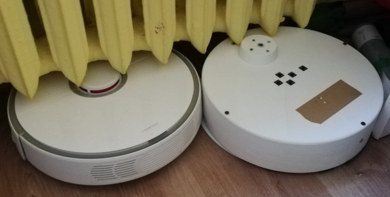
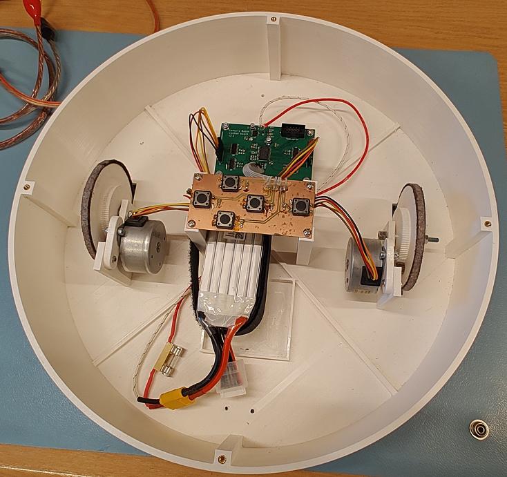
seal is supposed to be printed in TPU.
after printing, it shall be glued to a bottom part with CA glue.
without gluing it will be very hard to put things in place.
all the other elements can be printed in pretty much anything. my build was just in regular, white PLA.
it's recommend to put some felt under from and rear edges of the bottom part. it's also worth gluing a thin strip of felt around wheels' external circumference. this will protect floors from sharp edges and decrease the amount of noise, on flat floors.
while the seal is optional, it's highly recommended to silence vibrations.
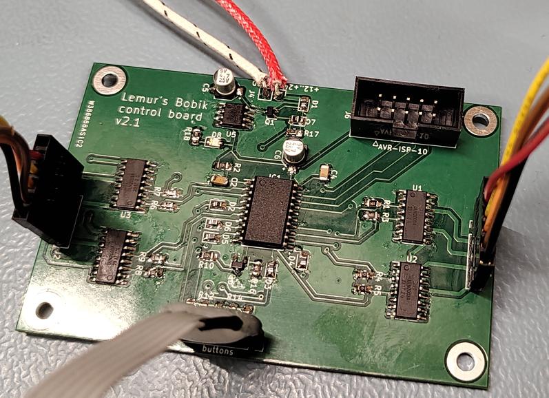
for electronic components checkout BOM, generated by builds, namely:
board/hw/control/build/bom.csv
board/hw/buttons/build/bom.csvscrews (especially bottom one) are hard to reach. in a hindsight whole engine-wheel module should have been reworked. engines could drive wheels directly, and me mounted with threaded inserts. this would simplify things a lot, and removed noisy gears altogether.
on top panel there should be more LEDs. these shall indicate:
it should be possible to check batter status w/o opening enclosure and disconnecting it. currently it's very absorbing and inconvenient.
programming via AVR's ISP is annoying and requires disassembly. as of writing these words (HW v2.1) it also requires unplugging main battery (to be fixed in next HW release). OTA re-flashing would be an improvement.
ATtinty2313 in current setting does not have enough pins to provide any feedback (even LED blinking).
more powerful µC should be used instead, that'd allow for serial (or BTLE) port debugging, to monitor state.
on top of that in-system gdb would save time for finding stupid mistakes.
this would greatly simplify finding issues and diagnosing inconveniences, that currently require a lot of fuss and re-flashing.
desktop printer engines used require unusual voltage (here: 24V, 0.35A). they are also quite weak (here: can easily be stopped with 2 fingers). more powerful NEMA 17 engines would be far superior choice. using bipolar steppers would also allow to use off the shelve stepper drivers and provide more torque.
| Qty | Value | Footprint | References |
|---|---|---|---|
| 10 | 100kR | Resistor_SMD:R_0805_2012Metric_Pad1.20x1.40mm_HandSolder | R1, R3, R4, R5, R6, R7, R8, R9, R16, R17 |
| 7 | 10kR | Resistor_SMD:R_0805_2012Metric_Pad1.20x1.40mm_HandSolder | R2, R10, R11, R12, R13, R14, R15 |
| 7 | TS418C | Diode_SMD:D_0805_2012Metric | D1, D2, D3, D4, D5, D6, D9 |
| 4 | M3 | MountingHole:MountingHole_3.2mm_M3_Pad_TopBottom | 1, 2, 3, 4 |
| 4 | ULN2003A | Package_SO:SOIC-16_3.9x9.9mm_P1.27mm | U1, U2, U3, U4 |
| 2 | 100nF | Capacitor_SMD:C_1206_3216Metric_Pad1.33x1.80mm_HandSolder | C2, C4 |
| 2 | 4.7µF | Capacitor_SMD:CP_Elec_4x5.8 | C5, C6 |
| 1 | 1kR | Resistor_SMD:R_0805_2012Metric_Pad1.20x1.40mm_HandSolder | R18 |
| 1 | 2N7002 | Package_TO_SOT_SMD:SOT-23 | Q3 |
| 1 | AVR-ISP-10 | Connector_IDC:IDC-Header_2x05_P2.54mm_Vertical | J6 |
| 1 | BZY55B3v0-RYG | Diode_SMD:D_0805_2012Metric_Pad1.15x1.40mm_HandSolder | D7 |
| 1 | LED green | LED_SMD:LED_0805_2012Metric_Pad1.15x1.40mm_HandSolder | D8 |
| 1 | LM78L05_SO8 | Package_SO:SOIC-8_3.9x4.9mm_P1.27mm | U5 |
| 1 | MMFTP84W | Package_TO_SOT_SMD:SOT-323_SC-70 | Q1 |
| 1 | TINY2313 | Package_SO:SOIC-20W_7.5x12.8mm_P1.27mm | IC1 |
| 1 | buttons | Connector_PinSocket_2.54mm:PinSocket_1x06_P2.54mm_Vertical | J3 |
| 1 | power | Connector_PinHeader_2.54mm:PinHeader_1x02_P2.54mm_Vertical | J4 |
| 1 | stepper #1 | Connector_PinHeader_2.54mm:PinHeader_1x05_P2.54mm_Vertical | J1 |
| 1 | stepper #2 | Connector_PinHeader_2.54mm:PinHeader_1x05_P2.54mm_Vertical | J2 |
el-bart/lemurs_bobik
project of a toy for a 3-5 year child, that is aimed at learning basic programming skills. robot has 4 buttons for programming directions and one button to start it.


dbalsom/arduinoX86
An interface between an Arduino Due or Arduino GIGA and 8088, 8086, V20, V30, 186 or 286 CPUs

fehlfarbe/arduino-motorfocus
Arduino motorfocus with moonlite protocol for telescopes

Scottapotamas/zaphod-bot
A DIY high performance delta-bot for fun, and lightpainting...

AllYarnsAreBeautiful/ayab-hardware
Contains the schematics and layouts for the AYAB Arduino shield


codingcatgirl/split-flap-fae-pcb
Alternative drop-in replacement PCB for David Kingsman's split-flap display

palazzol/CyberamicControlCenter
Repo for docs and info about the Cyberamic Control Center
It measures 54.3 × 82.5 mm and has 2 copper layers, 1.6 mm thick.
48 parts, built around the ULN2003A and MMFTP84W. The full list of its parts is on this page, with links to each part's symbol and footprint where PCBKit's library has them.
From the el-bart/lemurs_bobik repository on GitHub, at the commit this page was made from: the board is board/hw/control/control.kicad_pcb and its schematic board/hw/buttons/buttons.kicad_sch. PCBKit opens the board in the browser, with nothing to install.
Its repository states no licence, so its author keeps all rights: ask el-bart before reusing the design.