2 layers82.6 × 76.9 mm

 eGuardianDev/atmegaStepperDriver2
Open source stepper driver powered by atmega328p chip. First prototype designed for used in 3D printer.
AtmegaStepperDriver is an open-source printed circuit board by eGuardianDev, from the eGuardianDev/atmegaStepperDriver repository on GitHub, published under the GPL-3.0 licence. It is a 2-layer board of 94.5 × 67.6 mm with 102 parts on 82 nets, routed with 454 tracks and 38 vias.
It is built around the ATMEGA328P-PU, BC547 and BC557, with the TIP41C and TIP42C among its other parts. Its parts include 23 resistors, 19 diodes, 19 transistors, 14 capacitors and 7 connectors. It belongs with the robots and motor control boards and the AVR (ATmega, ATtiny) boards of this library.


Open source stepper driver powered by Atmega chip
This project was design to be used in my Modul3D project.
Now It has its own project.
The idea to have simple, cheap, open source stepper driver for stepper motor
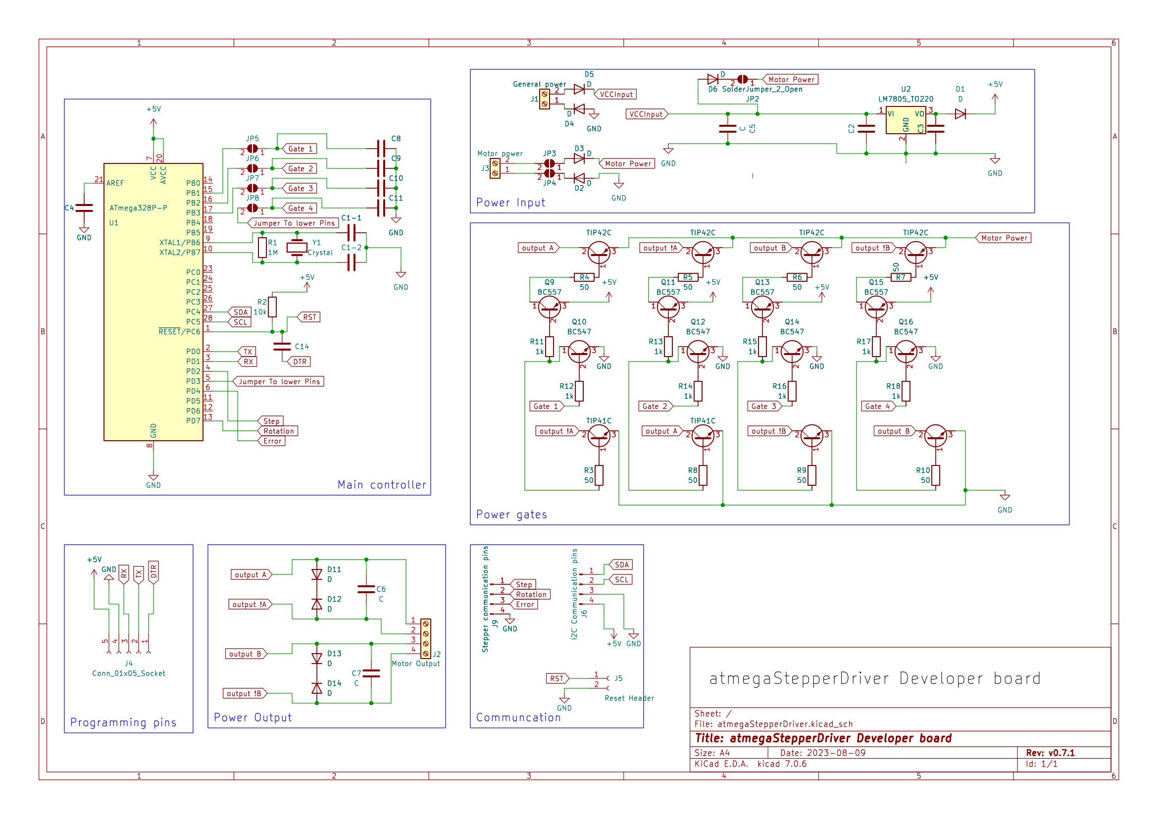
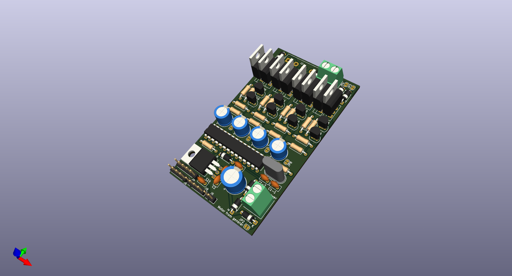
| Qty | Value | Footprint | References |
|---|---|---|---|
| 11 | SolderJumper_2_Open | Jumper:SolderJumper-2_P1.3mm_Open_RoundedPad1.0x1.5mm | AP_JP1, JP1, JP2, JP3, JP4, JP5, JP6, JP8, JP9, M_JP1, MP_JP1 |
| 10 | D | Diode_THT:D_A-405_P7.62mm_Horizontal | D1, D2, D3, D4, D5, D11, D12, D13, D14, m_D1 |
| 8 | 1k | Resistor_THT:R_Axial_DIN0207_L6.3mm_D2.5mm_P10.16mm_Horizontal | R4, R5, R8, R9, R12, R13, R22, R23 |
| 8 | 50 | Resistor_THT:R_Axial_DIN0207_L6.3mm_D2.5mm_P10.16mm_Horizontal | R3, R6, R7, R10, R11, R14, R21, R24 |
| 8 | C | Capacitor_THT:C_Disc_D5.0mm_W2.5mm_P2.50mm | C1-1, C1-2, C2, C3, C4, C6, C7, C14 |
| 8 | D | Diode_THT:D_DO-35_SOD27_P10.16mm_Horizontal | D8, D9, D10, D15, D16, D17, D18, D19 |
| 5 | C | Capacitor_THT:CP_Radial_D8.0mm_P3.80mm | C1, C2-1, C2-2, C2-3, C2-4 |
| 4 | BC547 | Package_TO_SOT_THT:TO-92_Inline_Wide | Q3, Q7, Q11, Q20 |
| 4 | BC557 | Package_TO_SOT_THT:TO-92_Inline_Wide | Q2, Q6, Q10, Q19 |
| 4 | TIP41C | Package_TO_SOT_THT:TO-220-3_Vertical | Q4, Q8, Q12, Q21 |
| 4 | TIP42C | Package_TO_SOT_THT:TO-220-3_Vertical | Q1, Q5, Q9, Q18 |
| 3 | 220 | Resistor_THT:R_Axial_DIN0207_L6.3mm_D2.5mm_P10.16mm_Horizontal | R18, R19, R25 |
| 3 | 250 | Resistor_THT:R_Axial_DIN0207_L6.3mm_D2.5mm_P10.16mm_Horizontal | 5V_R1, GND_R1, R20 |
| 2 | BC547 | Package_TO_SOT_THT:TO-92_Inline | Q13, Q17 |
| 1 | 10k | Resistor_THT:R_Axial_DIN0207_L6.3mm_D2.5mm_P10.16mm_Horizontal | R2 |
| 1 | 1M | Resistor_THT:R_Axial_DIN0207_L6.3mm_D2.5mm_P10.16mm_Horizontal | R1 |
| 1 | 4.3k | Resistor_THT:R_Axial_DIN0207_L6.3mm_D2.5mm_P10.16mm_Horizontal | R17 |
| 1 | 82k | Resistor_THT:R_Axial_DIN0207_L6.3mm_D2.5mm_P10.16mm_Horizontal | R16 |
| 1 | ATmega328P-P | Package_DIP:DIP-28_W7.62mm | U1 |
| 1 | BC557 | Package_TO_SOT_THT:TO-92_Inline | Q15 |
| 1 | C | Capacitor_THT:CP_Radial_D10.0mm_P5.00mm | C5 |
| 1 | Conn_01x03_Pin | Connector_PinHeader_2.54mm:PinHeader_1x03_P2.54mm_Vertical | TermoSocket1 |
| 1 | Crystal | Crystal:Crystal_HC49-U_Vertical | Y1 |
| 1 | FanSocket | Connector_PinHeader_2.54mm:PinHeader_1x02_P2.54mm_Vertical | FanSocket1 |
| 1 | General power | TerminalBlock_Phoenix:TerminalBlock_Phoenix_MKDS-1,5-2_1x02_P5.00mm_Horizontal | J1 |
| 1 | I2C Communication pins | Connector_PinHeader_2.54mm:PinHeader_1x04_P2.54mm_Vertical | J6 |
| 1 | LED | LED_THT:LED_D5.0mm | D7 |
| 1 | LM7805_TO220 | Package_TO_SOT_THT:TO-220-3_Vertical | U2 |
| 1 | LOGO | Logo:15x15Logo | G*** |
| 1 | Motor Output | TerminalBlock:TerminalBlock_bornier-4_P5.08mm | J2 |
| 1 | Motor power | TerminalBlock_Phoenix:TerminalBlock_Phoenix_MKDS-1,5-2_1x02_P5.00mm_Horizontal | J3 |
| 1 | Programming socket 01x06 | Connector_PinHeader_2.54mm:PinHeader_1x06_P2.54mm_Vertical | J8 |
| 1 | Reset Header | Connector_PinHeader_2.54mm:PinHeader_1x02_P2.54mm_Vertical | J5 |
| 1 | Stepper communication pins | Connector_PinHeader_2.54mm:PinHeader_1x04_P2.54mm_Vertical | J9 |
It measures 94.5 × 67.6 mm and has 2 copper layers, 1.6 mm thick.
102 parts, built around the ATMEGA328P-PU, BC547, BC557 and TIP41C. The full list of its parts is on this page, with links to each part's symbol and footprint where PCBKit's library has them.
From the eGuardianDev/atmegaStepperDriver repository on GitHub, at the commit this page was made from: the board is PCB/atmegaStepperDriver/atmegaStepperDriver.kicad_pcb and its schematic PCB/atmegaStepperDriver/Gate.kicad_sch. PCBKit opens the board in the browser, with nothing to install.
Its repository publishes it under the GPL-3.0 licence: you may reuse it on that licence's terms (keep the author's notice, and for a copyleft licence share your changes alike).

BojanSof/Lab-Bench-PSU
Laboratory bench power supply with switching preregulator and LDO.


DeniseViltes/dce-g5-proyecto_integrador
FIUBA - Electrónica - Taller de Diseño de Circuitos Electrónicos -Proyecto de diseño: Sistema de alimentación para aplicaciones industriales y automotrices

bluesyann/tripico-psu
3-Channels Raspberry Pico-based smart power supply. Can run as standalone power supply (V or I controlled), run I-V sweeps decribed in yaml files, or run as a passive ammeter/voltmeter


EvansCesilThomas/Tone_Controls_and_Sampling
3-in-1 (Overdrive, Distortion, Fuzz) effects for guitar (PCB is WIP) Proposed realtime audio sampling and pitch-sihting for a synthesizer functionality (WIP)