2 layers91 × 77.5 mm

 eflukx/Stepcraft-GRBLizer15
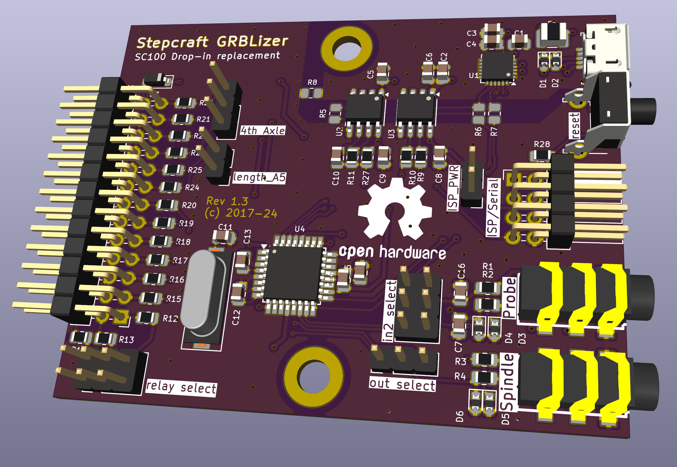
Replacement ('Arduino') controller that fits inside a Stepcraft CNC machine. Comptatible with GRBL and EstlCAM
Stepcraft controller is an open-source printed circuit board by eflukx, from the eflukx/Stepcraft-GRBLizer repository on GitHub. It is a 2-layer board of 68 × 54 mm with 71 parts on 90 nets, routed with 485 tracks and 174 vias.
It is built around the ATMEGA328P-AU, CP2102N-EK and ADUM1201BR, with the 1N5819W among its other parts. Its parts include 28 resistors, 16 capacitors, 9 connectors, 7 diodes and 4 ICs. It belongs with the robots and motor control boards and the AVR (ATmega, ATtiny) boards of this library.


A GRBL compatible controller for use as a drop-in replacement for the SC100 USB standard controller deliverd with Stepcraft CNC machines. This Arduino Uno compatible controller is wired conforming the GRL v0.9+ standard. The controller can be used with the GRBL firmware and with EstlCAM.
Alvast een leuk plaatje:
Access the interactive bom directly using this link!
Notes kindly provided by Albin Stigö on getting GRBL v1.1 working with the GRBLizer board.
Tested on Stepcraft 420, but probably works with most other Stepcraft types.
Install GRBL in the usual way. However you need to make some changes in config.h and cpu_map.h.
/* cpu_map.h */

// The Stepcraft has all limits on one pin.
#define X_LIMIT_BIT    1  // Uno Digital Pin 9
#define Y_LIMIT_BIT    1  // Uno Digital Pin 9
#define Z_LIMIT_BIT 1 // Uno Digital Pin 9/* config.h */
// Since all limit switches end up being shared on one pin,
// we can only home one direction at a time.
#define HOMING_CYCLE_0 (1<<Z_AXIS) // REQUIRED: First move Z to clear workspace.
#define HOMING_CYCLE_1 (1<<Y_AXIS) // OPTIONAL: Then move X,Y at the same time.
#define HOMING_CYCLE_2 (1<<X_AXIS) // OPTIONAL: Uncomment and add axes mask to enable
// The stop output of the Stepcraft board is inverted to what GRBL expects.
// However you simply can't swap the switch because the driver board will also
// disable the motors so nothing will move.
#define INVERT_CONTROL_PIN_MASK (1<<CONTROL_RESET_BIT) // Default disabled.I haven't done a lot of fine tuning but these seems to work well enough.
$0 = 50				(Step pulse time, microseconds)
$1 = 100			(Step idle delay, milliseconds)
$2 = 0				(Step pulse invert, mask)
$3 = 0				(Step direction invert, mask)
$4 = 1				(Invert step enable pin, boolean)
$5 = 1				(Invert limit pins, boolean)
$6 = 0				(Invert probe pin, boolean)
$10 = 1				(Status report options, mask)
$11 = 0.010			(Junction deviation, millimeters)
$12 = 0.002			(Arc tolerance, millimeters)
$13 = 0				(Report in inches, boolean)
$20 = 0				(Soft limits enable, boolean)
$21 = 0				(Hard limits enable, boolean)
$22 = 1				(Homing cycle enable, boolean)
$23 = 1				(Homing direction invert, mask)
$24 = 120.000		(Homing locate feed rate, mm/min)
$25 = 900.000		(Homing search seek rate, mm/min)
$26 = 250			(Homing switch debounce delay, milliseconds)
$27 = 1.000			(Homing switch pull-off distance, millimeters)
$30 = 1000			(Maximum spindle speed, RPM)
$31 = 0				(Minimum spindle speed, RPM)
$32 = 0				(Laser-mode enable, boolean)
$100 = 133.333		(X-axis travel resolution, step/mm)
$101 = 133.333 (Y-axis travel resolution, step/mm)| Qty | Value | Footprint | References |
|---|---|---|---|
| 22 | 100 | Resistor_SMD:R_0805_2012Metric | R1, R2, R10, R11, R12, R13, R14, R15, R16, R17, R18, R19, R20, R21, R22, R23 +6 |
| 10 | 100n | Capacitor_SMD:C_0805_2012Metric | C2, C3, C5, C6, C8, C9, C10, C13, C14, C15 |
| 6 | Littelfuse PESD0603-240 | Diode_SMD:D_0603_1608Metric | D1, D2, D3, D4, D5, D6 |
| 2 | 0 (DNP) | Resistor_SMD:R_0805_2012Metric | R5, R8 |
| 2 | 100 (DNP) | Resistor_SMD:R_0805_2012Metric | R6, R7 |
| 2 | 10n | Capacitor_SMD:C_0805_2012Metric | C7, C16 |
| 2 | 1u | Capacitor_SMD:C_0805_2012Metric | C1, C4 |
| 2 | 22p | Capacitor_SMD:C_0805_2012Metric | C11, C12 |
| 2 | ADuM1201BR | Package_SO:SOIC-8_3.9x4.9mm_P1.27mm | U2, U3 |
| 1 | 10k | Resistor_SMD:R_0805_2012Metric | R27 |
| 1 | 16MHz | Crystal:Crystal_SMD_HC49-SD | Y1 |
| 1 | 1N5819W | Diode_SMD:D_SOD-123 | D7 |
| 1 | 300 | Resistor_SMD:R_0805_2012Metric | R28 |
| 1 | 4th Axle | Connector_PinHeader_2.54mm:PinHeader_1x03_P2.54mm_Vertical | J10 |
| 1 | ATMEGA328P-AU | Package_QFP:TQFP-32_7x7mm_P0.8mm | U4 |
| 1 | CP2102N | Package_DFN_QFN:QFN-24-1EP_4x4mm_P0.5mm_EP2.6x2.6mm | U1 |
| 1 | ISP/Serial | Connector_PinHeader_2.54mm:PinHeader_2x04_P2.54mm_Horizontal | J8 |
| 1 | ISP_PWR | Connector_PinHeader_2.54mm:PinHeader_1x02_P2.54mm_Vertical | JP1 |
| 1 | Polyfuse_Small | Fuse:Fuse_1210_3225Metric | F1 |
| 1 | Probe | w_conn_av:jack_3.5_pj313d-smt | J2 |
| 1 | Spindle | w_conn_av:jack_3.5_pj313d-smt | J3 |
| 1 | UPDATE TO USB C | iotta_footprints:USB_Micro-B_2_Holes | J1 |
| 1 | X1 | iotta_footprints:Stepcraft_SC100_Controller_Board | J9 |
| 1 | in2 select | Connector_PinHeader_2.54mm:PinHeader_2x03_P2.54mm_Vertical | J11 |
| 1 | length_A5 | Connector_PinHeader_2.54mm:PinHeader_1x02_P2.54mm_Vertical | JP2 |
| 1 | out select | Connector_PinHeader_2.54mm:PinHeader_1x03_P2.54mm_Vertical | J4 |
| 1 | relay select | Connector_PinHeader_2.54mm:PinHeader_2x03_P2.54mm_Vertical | J6 |
| 1 | reset | Button_Switch_THT:SW_Tactile_SPST_Angled_PTS645Vx58-2LFS | SW1 |
The 69 most common of 71 parts.
It measures 68 × 54 mm and has 2 copper layers, 1.6 mm thick.
71 parts, built around the ATMEGA328P-AU, CP2102N-EK, ADUM1201BR and 1N5819W. The full list of its parts is on this page, with links to each part's symbol and footprint where PCBKit's library has them.
From the eflukx/Stepcraft-GRBLizer repository on GitHub, at the commit this page was made from: the board is stepcraft_controller.kicad_pcb and its schematic stepcraft_controller.kicad_sch. PCBKit opens the board in the browser, with nothing to install.
Its repository states no licence, so its author keeps all rights: ask eflukx before reusing the design.


