
2 layers231.1 × 106.7 mm

 EEprotocol/LEFT_Parade2
A compact device used by left hand
LEFT Parade is an open-source printed circuit board by EEprotocol, from the EEprotocol/LEFT_Parade repository on GitHub, published under the MIT licence. It is a 2-layer board of 86 × 72.5 mm with 40 parts on 31 nets, routed with 350 tracks and 8 vias.
It is built around the 74LS139PC. Its parts include 17 switches, 11 diodes, 3 capacitors, 2 ICs and 1 resistor. It belongs with the ESP32, SAM D and SAM and RISC-V boards of this library.
This is a so-called left-hand device.
You can also use it with your right hand.
It is intended for situations where you use a pen display tablet or similar device with one of your hand and want to trigger macros with the other hand.
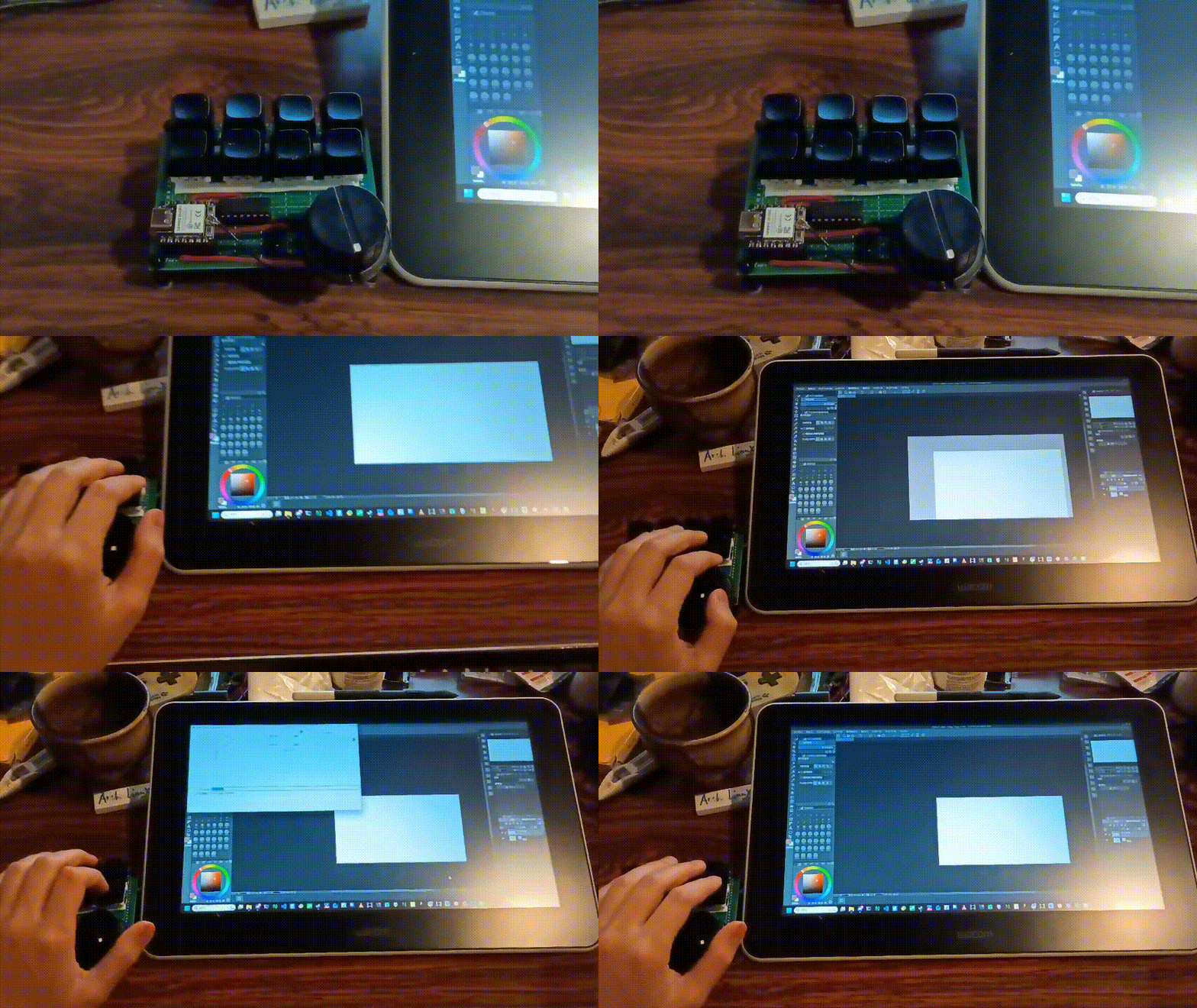
| Component | Price (JPY) |
|---|---|
| PCB | 110 |
| Rotary encoder (ec11e15244g1) | 550 |
| Knob | 190 |
| ESP32-C3 | 1,080 |
| Keycap × 8 | 70 |
| Key switch × 8 | 330 |
| Battery | 450 |
| Demultiplexer SN74HC139N | 135 |
| DIP socket (8 × 2 rows) | 135 |
| Pin socket (8 pin) × 2 | 136 |
| Total | 3,186 |
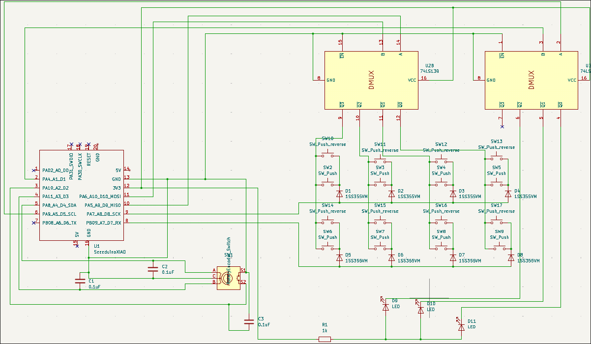 The annotation of the parts on the PCB corresponds to the circuit diagram.
I made a place for the LED D11, but system does not use it.
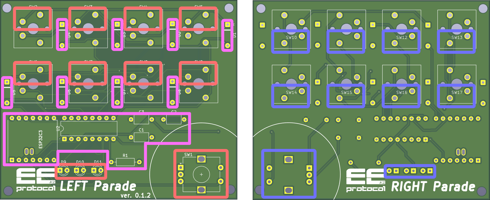 If you make this device as Left hand device, you solder on the parts surronded by red and purple line,
and If you make it as right hand device, solder on the parts with purple and blue line.
The component mounting side aligns with the side marked with the respective part indicators.
Install Arduino IDE on your PC, e.g.
yay -S arduino-ide
Install library Mystfit/ESP32-BLE-CompositeHID.
Upload to leftandmechv5_PCB/leftandmechv5_PCB.ino to ESP32-C3.
You can set the macro in the preamble of the .ino scripts.
const uint8_t KC_SAVE[] = { 0x01, KEY_S };
const uint8_t KC_COPY[] = { 0x01, KEY_C };
const uint8_t KC_PASTE[] = { 0x01, KEY_V };
const uint8_t KC_DELETE[] = { 0x4c };
const uint8_t KC_m[] = { KEY_M };
const uint8_t KC_UNDO[] = { 0x01, KEY_Z };
const uint8_t KC_ESC[] = { KEY_ESC };
const uint8_t KC_UP[] = { KEY_UP };
const uint8_t KC_DOWN[] = { KEY_DOWN };
const uint8_t KC_LEFT[] = { KEY_LEFT };
const uint8_t KC_RIGHT[] = { KEY_RIGHT };
const uint8_t KC_PAGE_NEXT[] = { 0x01, KEY_RIGHT };
const uint8_t KC_PAGE_BACK[] = { 0x01, KEY_LEFT };
The list of uint8_t refers the operation s.t. Ctrl+S, ESC, or Delete. This list of macro is commonly used in the two mode.
In the list, terms of keys except the last term is regarded as modifier keys s.t. Alt, Ctrl or Shift.
For this mode, you can set the assignment with keymap[].
const keyMapEntry keymap[] = {
  { 1, { KC_SAVE, 2 } },
  { 54, { KC_ESC, 1 } },
  { 4, { KC_COPY, 2 } },
  { 7, { KC_PASTE, 2 } },
  { 2, { KC_DELETE, 1 } },
  { 6, { KC_m, 1 } },
  { 28, { KC_UNDO, 2 } },
  { 18, { KC_UP, 1 } },
  { 9, { KC_DOWN, 1 } },
  { 27, { KC_LEFT, 1 } },
  { 3, { KC_RIGHT, 1 } },
  { 8, { KC_PAGE_NEXT, 2 } },
  { 20, { KC_PAGE_BACK, 2 } }
};
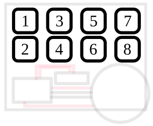
The first number refers the keyID of the combinaiton, second string refers the macro which you defined above and the last number refers the number of the element of the list of the macro. You can calculate the keyID as following:
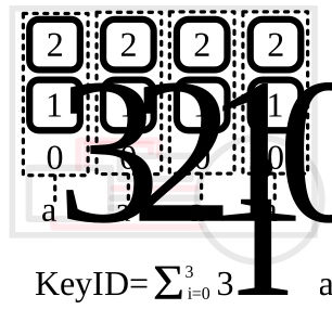
2 refers the upper key, 1 refers the lower key, 0 refers no pushed. In this mode, it is prohibited to push 2 keys in a column.
const keyMapEntry direct_key[] = {
  { 1, { KC_LEFT, 1 } },
  { 2, { KC_UP, 1 } },
  { 3, { KC_DOWN, 1 } },
  { 5, { KC_RIGHT, 1 } }
};
The key ID which plades the first number corresponds to the following assignment:
If you have something to ask, please mail to keik4656@gmail.com.
| Qty | Value | Footprint | References |
|---|---|---|---|
| 8 | 1SS355VM | Diode_THT:D_A-405_P7.62mm_Horizontal | D1, D2, D3, D4, D5, D6, D7, D8 |
| 8 | SW_Push | Button_Switch_Keyboard:SW_Cherry_MX_1.00u_PCB | SW2, SW3, SW4, SW5, SW6, SW7, SW8, SW9 |
| 8 | SW_Push_reverse | esp32_xiao:SW_Cherry_MX_1.00u_PCB_reverse | SW10, SW11, SW12, SW13, SW14, SW15, SW16, SW17 |
| 3 | , , | ||
| 3 | 0.1uF | Capacitor_THT:C_Axial_L5.1mm_D3.1mm_P7.50mm_Horizontal | C1, C2, C3 |
| 3 | LED | LED_THT:LED_D3.0mm_Clear | D9, D10, D11 |
| 1 | 1k | Resistor_THT:R_Axial_DIN0207_L6.3mm_D2.5mm_P10.16mm_Horizontal | R1 |
| 1 | 74LS139 | Package_DIP:CERDIP-16_W7.62mm_SideBrazed | U2 |
| 1 | LOGO | illust:normaltype_bit | G*** |
| 1 | LOGO | illust:normaltype_bit_reverse | G*** |
| 1 | RotaryEncoder_Switch | Rotary_Encoder:RotaryEncoder_Alps_EC12E-Switch_Vertical_H20mm | SW1 |
| 1 | SeeeduinoXIAO | esp32_xiao:ESP32C3_Footprint | U1 |
The 39 most common of 40 parts.
It measures 86 × 72.5 mm and has 2 copper layers, 1.6 mm thick.
40 parts, built around the 74LS139PC. The full list of its parts is on this page, with links to each part's symbol and footprint where PCBKit's library has them.
From the EEprotocol/LEFT_Parade repository on GitHub, at the commit this page was made from: the board is LEFT_Parade_kicad/LEFT_Parade.kicad_pcb and its schematic LEFT_Parade_kicad/LEFT_Parade.kicad_sch. PCBKit opens the board in the browser, with nothing to install.
Its repository publishes it under the MIT licence: you may reuse it on that licence's terms (keep the author's notice, and for a copyleft licence share your changes alike).

mudmin/AnotherMaker
This is where I will store code snippets for AnotherMaker Videos


The-Invent0r/8-bit-Computer-PCB
These are the KiCAD files for my 8-Bit Computer.


MouseBiteLabs/Super-Nintendo-Cartridges
A collection of Super Nintendo cartridge circuit boards

btb/80ColumnCard
An Apple II 80-Column Card. Based on the Videx Videoterm