

2 layers200 × 100 mm

 eccentricOrange/bt-speaker4
A Simple Two-way Analog Speaker Amplifier
Analog audio is an open-source printed circuit board by eccentricOrange, from the eccentricOrange/bt-speaker repository on GitHub. It is a 2-layer board of 85 × 70.5 mm with 44 parts on 28 nets, routed with 230 tracks and 49 vias.
It is built around the TIP31 and TIP32. Its parts include 20 resistors, 8 transistors, 7 connectors, 4 capacitors and 2 ICs. It belongs with the audio and music boards of this library.
This is a simple analog speaker driver, mostly driven simply by the goal of learning more about this field. This work was published in the 2025 Innovations in Power and Advanced Computing Technologies (i-PACT) conference. Please consider citing our paper, available on IEEEXplore at doi.org/10.1109/i-PACT65952.2025.11307947.
@INPROCEEDINGS{11307947,
  author={Verma, Anuj and Senthilkumar, Snehasree and A, Sharmila},
  booktitle={2025 Innovations in Power and Advanced Computing Technologies (i-PACT)},
  title={Design and Implementation of a Two-Way Speaker Amplifier},
  year={2025},
  volume={},
  number={},
  pages={1-9},
  keywords={Technological innovation;Filters;System performance;Stability criteria;Power amplifiers;Distortion;Topology;Thermal analysis;Thermal stability;Gain;analog;speaker;amplifier;filter;PCB design},
  doi={10.1109/i-PACT65952.2025.11307947},
  ISSN={},
  month={Sep.}
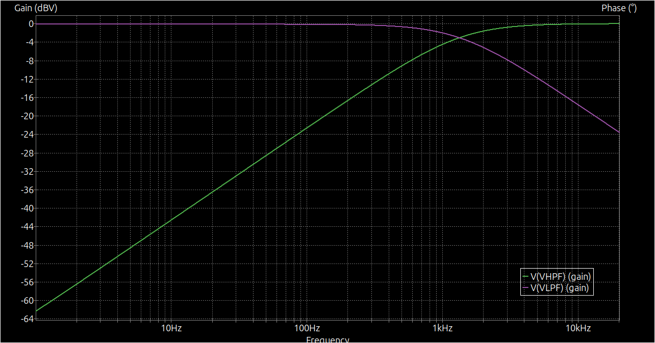
}The driver is designed to support two drivers, one for bass and one for treble. The cross-over frequency is 1326 Hz, and is achieved by using simple first order filters.
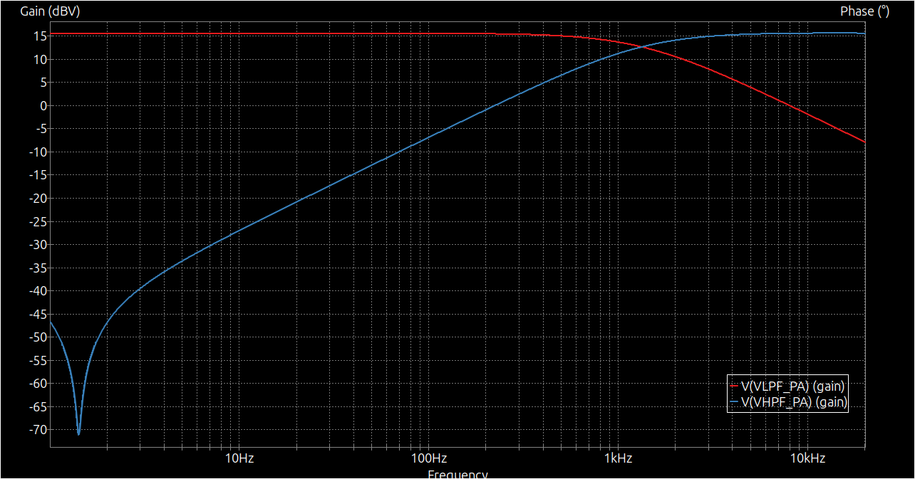
The input voltage is amplified by a factor of 6, using a simple non-inverting amplifier (LM741 op-amp). It is expected that the input voltage is around 1 V amplitude (2 Vpp), delivered by a 3.5 mm audio connector.
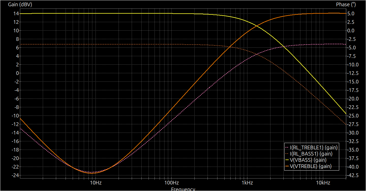
The next stage is a power amplifier, which is a simple class AB amplifier, that allows each driver to draw up to about 5W. Each driver is expected to have an impedance of 4 Ohm. TIP31 and TIP32 power transistors are used.
The PCB takes a single 24VDC 1A barrel jack input, and divides the voltage into 12VDC and -12VDC using a simple voltage divider.
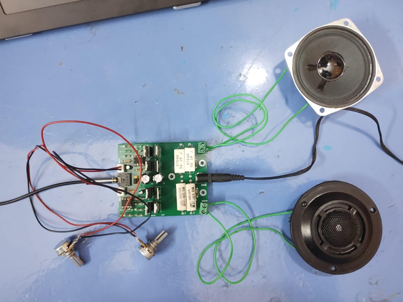
The final assembled two-way speaker system with custom PCB is shown below
| Qty | Value | Footprint | References |
|---|---|---|---|
| 8 | 1k | Resistor_THT:R_Axial_DIN0207_L6.3mm_D2.5mm_P7.62mm_Horizontal | R7, R8, R9, R10, R13, R14, R15, R16 |
| 4 | 10k | Resistor_THT:R_Axial_DIN0207_L6.3mm_D2.5mm_P7.62mm_Horizontal | R5, R6, R19, R20 |
| 4 | TIP31 | Package_TO_SOT_THT:TO-220-3_Vertical | Q1, Q2, Q6, Q7 |
| 4 | TIP32 | Package_TO_SOT_THT:TO-220-3_Vertical | Q3, Q4, Q5, Q8 |
| 3 | MountingHole_Pad | MountingHole:MountingHole_3.2mm_M3_Pad_Via | H1, H2, H3 |
| 2 | 0.5R | Resistor_THT:R_Axial_Power_L25.0mm_W6.4mm_P30.48mm | R11, R12 |
| 2 | 10uF | Capacitor_THT:C_Radial_D6.3mm_H11.0mm_P2.50mm | C1, C2 |
| 2 | 12R | Resistor_THT:R_Axial_DIN0207_L6.3mm_D2.5mm_P7.62mm_Horizontal | R1, R2 |
| 2 | 1R | Resistor_THT:R_Axial_Power_L25.0mm_W6.4mm_P30.48mm | R17, R18 |
| 2 | 1mF | Capacitor_THT:C_Radial_D10.0mm_H12.5mm_P5.00mm | C3, C4 |
| 2 | 750R | Resistor_THT:R_Axial_DIN0207_L6.3mm_D2.5mm_P7.62mm_Horizontal | R3, R4 |
| 2 | LM741 | Package_DIP:DIP-8_W7.62mm_Socket | U1, U2 |
| 2 | VOL-T | Connector_JST:JST_EH_B2B-EH-A_1x02_P2.50mm_Vertical | J3, J4 |
| 1 | 24VDC | Connector_BarrelJack:BarrelJack_GCT_DCJ200-10-A_Horizontal | J2 |
| 1 | AudioJack5 | Connector_Audio:Jack_3.5mm_CUI_SJ1-3525N_Horizontal | J1 |
| 1 | BASS | TerminalBlock:TerminalBlock_bornier-2_P5.08mm | J5 |
| 1 | Channel | Connector_PinHeader_2.54mm:PinHeader_1x03_P2.54mm_Vertical | J7 |
| 1 | TREBLE | TerminalBlock:TerminalBlock_bornier-2_P5.08mm | J6 |
It measures 85 × 70.5 mm and has 2 copper layers, 1.6 mm thick.
44 parts, built around the TIP31 and TIP32. The full list of its parts is on this page, with links to each part's symbol and footprint where PCBKit's library has them.
From the eccentricOrange/bt-speaker repository on GitHub, at the commit this page was made from: the board is pcbs/analog-audio/analog-audio.kicad_pcb and its schematic pcbs/analog-audio/analog-audio.kicad_sch. PCBKit opens the board in the browser, with nothing to install.
Its repository states no licence, so its author keeps all rights: ask eccentricOrange before reusing the design.


Hyperwiper/Hyperwiper
Data flow: audio source such as music player or smartphone connected to beat detector as embedded

fberni21/taller-circuitos
FIUBA - Electrónica - Taller de Diseño de Circuitos Electrónicos
