4 layers160 × 100 mm
OSM env01
devtank-ltd/kicad_osm_env01
This documentation describes Open Hardware and is Licensed under CERN-OHL-W v2.
243 parts
 ebertmx/DODGECLOCK
A shot clock system for competitve dodgeball. The system consists of two devices: display and controller.
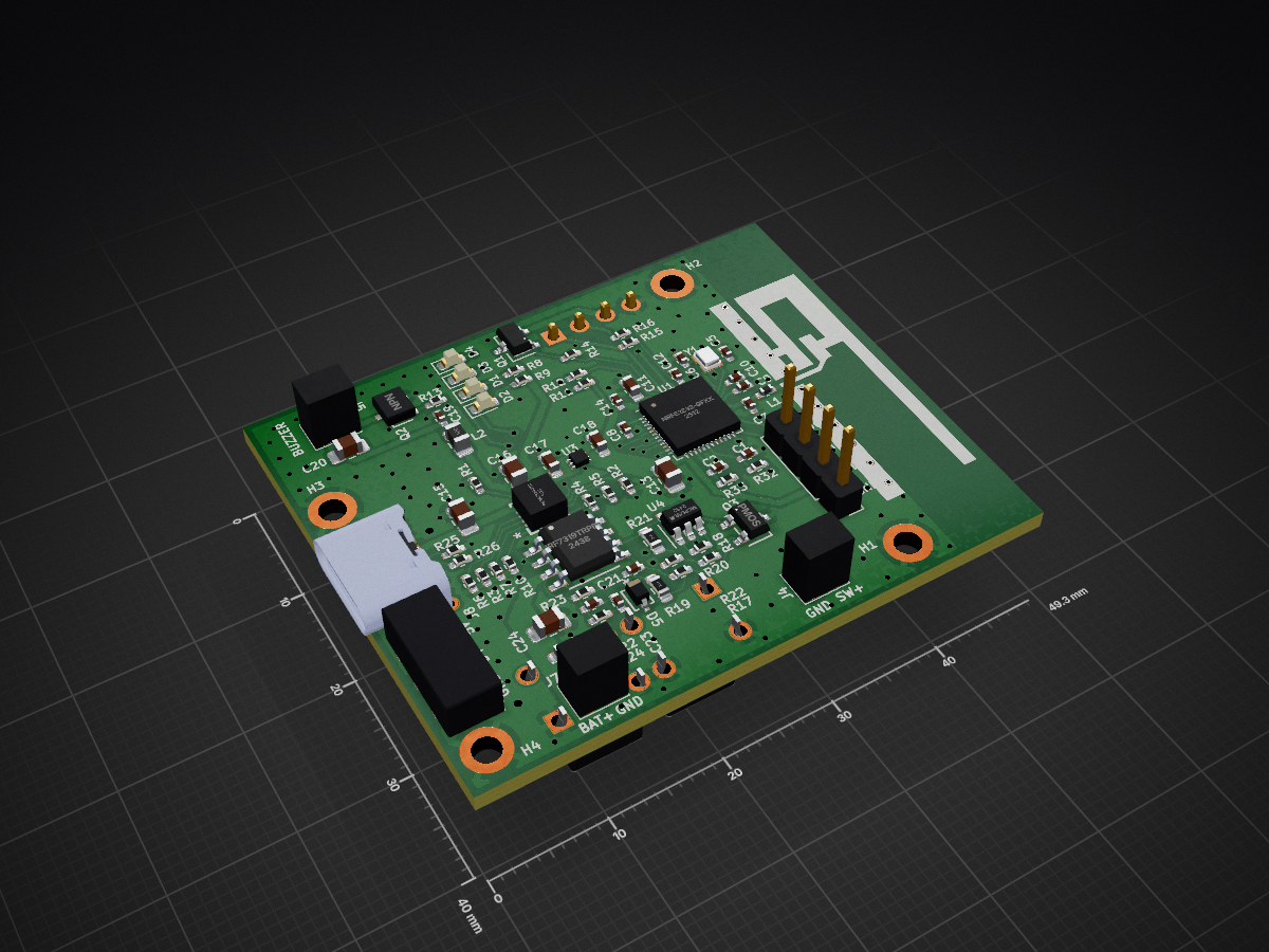
BLE REMOTE is an open-source printed circuit board by ebertmx, from the ebertmx/DODGECLOCK repository on GitHub, published under the MIT licence. It is a 4-layer board of 49.3 × 40 mm with 82 parts on 77 nets, routed with 410 tracks and 186 vias.
It is built around the IRF7319TRPBF, MIC5528-3.3YMT-TR and 1N4148WX-TP, with the BSS806NEH6327XTSA1 among its other parts. Its parts include 28 resistors, 23 capacitors, 8 connectors, 5 ICs and 5 diodes. It belongs with the radio and wireless boards and the nRF52 and nRF5x boards of this library.


A shot clock system for competitve dodgeball. The system consists of two devices: display and controller.
This project is in progress...
A first iteration PCB was order and successfully programmed. The firmware was tested with the MCU powered externally (without battery or linear regulator).
The BLE functionality on the PCB was not functional when powered by battery. Trouble shooting revealed the linear regulator is not acceptable for the current requirement of the antenna. Voltage spike when the antenna turns on crash the MCU.
A second iteration board is in progress to improve performance and fix the power delivery problems.
The display 7-segment frame was pritned with TPU and succesffuly passed all impact tests. A nrf52 dongle will be used as the MCU for the display to save on time, costs, and assembly requirements. The LED strip, power supply, and nrf52 dongle have been tested in a bench top environment succeffully.
The controller device includes
The controller devices is held by the ref and used to control the shot clock count.
The device acts as a peripheral/server. It accepts secure connections and provide clock and state information. This device is battery powered; thus, it tries to mimize power at all times. The device prioritizes the built in LCD and user controls over the BLE connection; consequently, the ref always knows the correct shot clock time and can control the state.
The display device includes
The display device is plugged into a wall outlet or similar power source and mounted within view of the court. The players and ref can reference this display.
This device acts as a central/client. It initiates a secure connection with the controller and recieves time and state information if possible. If a connection is lost of cannot be estabilished it enters a dormant state and displays nothing. Otherwise, it displays the current count down time from the controller.
| Qty | Value | Footprint | References |
|---|---|---|---|
| 6 | 2k | Resistor_SMD:R_0402_1005Metric_Pad0.72x0.64mm_HandSolder | R8, R9, R11, R12, R32, R33 |
| 5 | 0R | Resistor_SMD:R_0402_1005Metric_Pad0.72x0.64mm_HandSolder | R2, R3, R4, R5, R6 |
| 4 | 100k | Resistor_SMD:R_0402_1005Metric_Pad0.72x0.64mm_HandSolder | R17, R18, R22, R23 |
| 4 | 100nF | Capacitor_SMD:C_0402_1005Metric_Pad0.74x0.62mm_HandSolder | C8, C12, C14, C22 |
| 4 | 4.7uF | Capacitor_SMD:C_0805_2012Metric_Pad1.18x1.45mm_HandSolder | C13, C16, C20, C24 |
| 4 | LED | LED_SMD:LED_0603_1608Metric | D1, D2, D3, D4 |
| 4 | MountingHole_Pad | MountingHole:MountingHole_2.2mm_M2_DIN965_Pad | H1, H2, H3, H4 |
| 3 | 10uF | Capacitor_SMD:C_0402_1005Metric_Pad0.74x0.62mm_HandSolder | C1, C2, C21 |
| 3 | 2.2uF | Capacitor_SMD:C_0603_1608Metric_Pad1.08x0.95mm_HandSolder | C17, C18, C25 |
| 3 | 47k | Resistor_SMD:R_0402_1005Metric_Pad0.72x0.64mm_HandSolder | R14, R15, R16 |
| 2 | 10k | Resistor_SMD:R_0402_1005Metric_Pad0.72x0.64mm_HandSolder | R10, R24 |
| 2 | 10pF | Capacitor_SMD:C_0402_1005Metric_Pad0.74x0.62mm_HandSolder | C5, C6 |
| 2 | 5.1k | Resistor_SMD:R_0402_1005Metric_Pad0.72x0.64mm_HandSolder | R25, R26 |
| 2 | SW_Push | _Parts:SW_TS02-66-120-BK-260-LCR-D | SW1, SW2 |
| 1 | 0.8pF | Capacitor_SMD:C_0402_1005Metric_Pad0.74x0.62mm_HandSolder | C7 |
| 1 | 100pF | Capacitor_SMD:C_0402_1005Metric_Pad0.74x0.62mm_HandSolder | C10 |
| 1 | 10uH | Inductor_SMD:L_0805_2012Metric_Pad1.15x1.40mm_HandSolder | L2 |
| 1 | 150k | Resistor_SMD:R_0603_1608Metric_Pad0.98x0.95mm_HandSolder | R21 |
| 1 | 1N4148WX-TP | _Parts:CR_SOD323_MCC-L | D5 |
| 1 | 1k | Resistor_SMD:R_0402_1005Metric_Pad0.72x0.64mm_HandSolder | R20 |
| 1 | 1nF | Capacitor_SMD:C_0402_1005Metric_Pad0.74x0.62mm_HandSolder | C19 |
| 1 | 1uF | Capacitor_SMD:C_0402_1005Metric_Pad0.74x0.62mm_HandSolder | C23 |
| 1 | 1uF | Capacitor_SMD:C_0805_2012Metric_Pad1.18x1.45mm_HandSolder | C15 |
| 1 | 1uF | Capacitor_SMD:C_0603_1608Metric_Pad1.08x0.95mm_HandSolder | C11 |
| 1 | 2.94k | Resistor_SMD:R_0402_1005Metric_Pad0.72x0.64mm_HandSolder | R1 |
| 1 | 220 | Resistor_SMD:R_0402_1005Metric_Pad0.72x0.64mm_HandSolder | R13 |
| 1 | 3.8nH | Inductor_SMD:L_0402_1005Metric_Pad0.77x0.64mm_HandSolder | L1 |
| 1 | 300k | Resistor_SMD:R_0603_1608Metric_Pad0.98x0.95mm_HandSolder | R19 |
| 1 | 4.32k | Resistor_SMD:R_0402_1005Metric_Pad0.72x0.64mm_HandSolder | R7 |
| 1 | BQ24232RGTR | _Parts:RGT0016C | U2 |
| 1 | BSS806NEH6327XTSA1 | _Parts:SOT-23-3L_AOS | Q1 |
| 1 | BUZZER | _Parts:2pad_conn_sm | J5 |
| 1 | Battery | _Parts:2pad_conn_sm | J7 |
| 1 | Crystal_GND24 | _Parts:OSC_XRCGB32M000F2P01R0 | Y1 |
| 1 | Display | _Parts:OLED_091 | J6 |
| 1 | IRF7319TRPBF | _Parts:TRANS_IRF7103TRPBF_INF | U5 |
| 1 | LED_STRIP | _Parts:3pad_conn | J3 |
| 1 | MCP65R41 | Package_TO_SOT_SMD:SOT-23-6 | U4 |
| 1 | MIC5528-3.3YMT-TR | _Parts:TDFN6_1P2X1P2_MCH | U3 |
| 1 | NC | Capacitor_SMD:C_0402_1005Metric_Pad0.74x0.62mm_HandSolder | C9 |
| 1 | NPN | _Parts:TRAN_SS8050-G_CIP | Q2 |
| 1 | PGRM | Connector_PinHeader_2.54mm:PinHeader_1x04_P2.54mm_Vertical | J1 |
| 1 | PMOS | _Parts:SOT-23-3L_AOS | Q3 |
| 1 | RESET | Connector_PinHeader_1.27mm:PinHeader_2x01_P1.27mm_Vertical_SMD | J2 |
| 1 | SWITCH | _Parts:2pad_conn_sm | J4 |
| 1 | SWRU120B | MyAntennas:SWRU120B | A1 |
| 1 | USBC | _Parts:GCT_USB4125-GF-A_REVA2 | J8 |
| 1 | nRF52832-QFxx | Package_DFN_QFN:QFN-48-1EP_6x6mm_P0.4mm_EP4.6x4.6mm | U1 |
It measures 49.3 × 40 mm and has 4 copper layers, 1.6 mm thick.
82 parts, built around the IRF7319TRPBF, MIC5528-3.3YMT-TR, 1N4148WX-TP and BSS806NEH6327XTSA1. The full list of its parts is on this page, with links to each part's symbol and footprint where PCBKit's library has them.
From the ebertmx/DODGECLOCK repository on GitHub, at the commit this page was made from: the board is _Electrical/BLE_REMOTE/BLE_REMOTE.kicad_pcb and its schematic _Electrical/BLE_REMOTE/BLEC_peripherals.kicad_sch. PCBKit opens the board in the browser, with nothing to install.
Its repository publishes it under the MIT licence: you may reuse it on that licence's terms (keep the author's notice, and for a copyleft licence share your changes alike).
devtank-ltd/kicad_osm_env01
This documentation describes Open Hardware and is Licensed under CERN-OHL-W v2.

gplanta/gplanta_raspizero_hat
Raspberry Pi Zero Sensor and PWM uHAT


benkuper/BenTo-Legacy
Legacy repository for the former BenTo-Club project