
2 layers
OpenMQTTGatewayPCB
ebrithiljonas/OMG_PCB
All in One PCB for the OpenMQTTGateway Project
36 parts7GPL-3.0
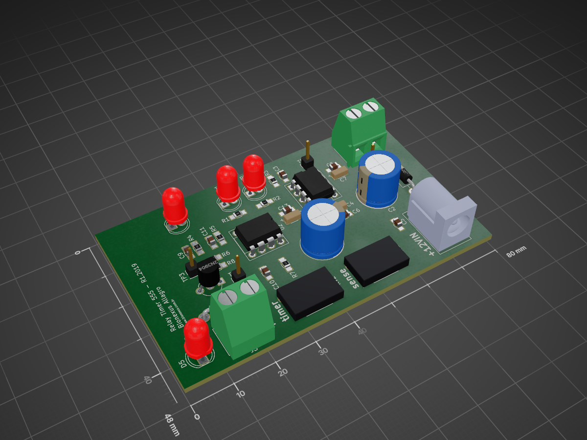
 eavcodes/relay-timer555
Adjustable timer circuit with 555 and relay
Relay timer555 is an open-source printed circuit board by eavcodes, from the eavcodes/relay-timer555 repository on GitHub, published under the MIT licence. It is a 2-layer board of 80 × 48 mm with 40 parts on 20 nets.
It is built around the IR204-A-L. Its parts include 13 capacitors, 9 resistors, 6 diodes, 3 connectors and 2 ICs. It belongs with the home automation and IoT boards of this library.
Adjustable timer circuit with 555 and relay switch
| Qty | Value | Footprint | References |
|---|---|---|---|
| 7 | 0.1uF | Capacitors_SMD:C_0805_HandSoldering | C3, C5, C6, C8, C9, C11, C13 |
| 4 | TestPoint | Pin_Headers:Pin_Header_Straight_1x01_Pitch2.54mm | TP1, TP2, TP3, TP4 |
| 3 | eav_footprints:c_pol_1206 | C4, C7, C12 | |
| 2 | 10k | Resistors_SMD:R_0805_HandSoldering | R2, R6 |
| 2 | 1k | Resistors_SMD:R_0805_HandSoldering | R5, R8 |
| 2 | 1k5 | Resistors_SMD:R_0805_HandSoldering | R4, R9 |
| 2 | 470uF | Capacitors_THT:CP_Radial_D10.0mm_P3.50mm | C2, C14 |
| 1 | 100k | Potentiometers:Potentiometer_WirePads_largePads | RV1 |
| 1 | 10nF | Capacitors_SMD:C_0805_HandSoldering | C10 |
| 1 | 120k | Resistors_SMD:R_0805_HandSoldering | R7 |
| 1 | 1M | Potentiometers:Potentiometer_WirePads_largePads | RV2 |
| 1 | 1N4004 | Diodes_THT:D_DO-41_SOD81_P10.16mm_Horizontal | D6 |
| 1 | 1N4007 | Diodes_THT:D_DO-41_SOD81_P10.16mm_Horizontal | D2 |
| 1 | 220R | Resistors_SMD:R_0805_HandSoldering | R1 |
| 1 | 2N3904 | TO_SOT_Packages_THT:TO-92_Inline_Wide | Q1 |
| 1 | 470R | Resistors_SMD:R_0805_HandSoldering | R3 |
| 1 | D_Photo | LEDs:LED_D5.0mm | D3 |
| 1 | IR204A | LEDs:LED_D5.0mm | D1 |
| 1 | LM555 | Housings_DIP:DIP-8_W7.62mm_Socket | U2 |
| 1 | LM741 | Housings_DIP:DIP-8_W7.62mm_Socket | U1 |
| 1 | ON | LEDs:LED_D5.0mm | D5 |
| 1 | PWRIN | Connectors:BARREL_JACK | J2 |
| 1 | PWROUT | Connectors_Terminal_Blocks:TerminalBlock_bornier-2_P5.08mm | J1 |
| 1 | RPORT | Connectors_Terminal_Blocks:TerminalBlock_bornier-2_P5.08mm | J3 |
| 1 | TRIG | LEDs:LED_D5.0mm | D4 |
It measures 80 × 48 mm and has 2 copper layers, 1.6 mm thick.
40 parts, built around the IR204-A-L. The full list of its parts is on this page, with links to each part's symbol and footprint where PCBKit's library has them.
From the eavcodes/relay-timer555 repository on GitHub, at the commit this page was made from: the board is sch/relay-timer555/relay-timer555.kicad_pcb. PCBKit opens the board in the browser, with nothing to install.
Its repository publishes it under the MIT licence: you may reuse it on that licence's terms (keep the author's notice, and for a copyleft licence share your changes alike).
ebrithiljonas/OMG_PCB
All in One PCB for the OpenMQTTGateway Project


bismarx-v1/Sumec-Remote
IR remote for MiniSumo, schematic and partial code was forked from p1rse

hitendravalhe/IR_sensor_pcb_design
This repository contains the design files and documentation for an Infrared (IR) sensor PCB with an integrated LM35 temperature sensor.

PostTenebrasLab/PTL-IR_remote
IR remote based on esp8266 with OTA, MQTT, web server, DHT22, brightness, IRM

