2 layers111.8 × 95.3 mm
 dylanmsu/Splitflap_Display1
software to drive a public split flap display
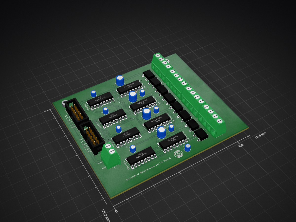
Splitflap is an open-source printed circuit board by dylanmsu, from the dylanmsu/Splitflap_Display repository on GitHub, published under the GPL-3.0 licence. It is a 2-layer board of 111.8 × 95.3 mm with 38 parts on 59 nets, routed with 762 tracks and 162 vias.
It is built around the SN754410NE, 74HC595 and CD4049UBE. Its parts include 12 capacitors, 8 ICs, 8 diodes and 5 connectors.


software to digtally drive a public splitflap display using arduino. The display is meant do be deployed in a steamtrain station where it reads the data from their server. This project is still in development and requires major improvements and code cleanup.
The included Arduino compatible library is designed to drive a complete split flap display board with 32 individual modules. There are also methods included to drive the individual split flaps with great control. You can for example call the method:
splitflaps.flipSegment(int segment);That line of code will flip the segment once. Or if you want more control, there is the method:
splitflaps.writeSegment(int segment, int state);It sets the state of the selected h-Bridge. There are (in the future) a bunch of example sketches with different use cases for the library. However, they all require at least one driver PCB to actually drive the split flap modules.
The driver PCBs can drive 8 splitflap modules at the same time, for that it uses 4 SN754410NE chips (L293D in version 4) that are driven by two 74HC595 shift registers. One shift registers drives the H-bridges, the other enables the outputs of the 8 H-Bridges so they dont waste unnecessary power. The communication protocol is quite simple. You have two serial data inputs in the input connector, one is to enable the individual H-Bridges (DiE, ClkE, LaE), the other is to drive the individual H-bridges (Di, Clk, La). They can be daisy-chained to drive an infinite number of splitflap modules.
To actually drive splitflap modules with it, open the arduino sketch named TestDriver. Connect the splitflap modules solenoid connections to the H-Bridge output pairs. Then connect the serial pins to the arduino pins listed in the sketch. and lastly connect 20v to the Vdd input connector. Upload the sketch, the splitflaps should be working.
| Qty | Value | Footprint | References |
|---|---|---|---|
| 8 | CP | Capacitor_THT:CP_Radial_D4.0mm_P2.00mm | C1, C2, C3, C4, C6, C7, C9, C10 |
| 8 | D_Bridge_+-AA | Diode_THT:Diode_Bridge_DIP-4_W7.62mm_P5.08mm | D1, D2, D3, D4, D5, D6, D7, D8 |
| 4 | CP | Capacitor_THT:CP_Radial_D6.3mm_P2.50mm | C5, C8, C11, C12 |
| 4 | SN754410NE | Package_DIP:DIP-16_W7.62mm_LongPads | U3, U4, U5, U6 |
| 4 | Screw_Terminal_01x04 | TerminalBlock:TerminalBlock_bornier-4_P5.08mm | J3, J4, J5, J6 |
| 2 | 74HC595 | Package_DIP:DIP-16_W7.62mm_LongPads | U1, U2 |
| 2 | CD4049UBE | Package_DIP:DIP-16_W7.62mm_LongPads | IC1, IC2 |
| 2 | Conn_02x06_Odd_Even | Connector_IDC:IDC-Header_2x06_P2.54mm_Vertical | INPUT J1, OUTPUT J2 |
| 1 | LOGO | maldegem:logo_maldegem2 | G*** |
| 1 | Screw_Terminal_01x02 | TerminalBlock:TerminalBlock_bornier-2_P5.08mm | J7 |
The 36 most common of 38 parts.
It measures 111.8 × 95.3 mm and has 2 copper layers, 1.6 mm thick.
38 parts, built around the SN754410NE, 74HC595 and CD4049UBE. The full list of its parts is on this page, with links to each part's symbol and footprint where PCBKit's library has them.
From the dylanmsu/Splitflap_Display repository on GitHub, at the commit this page was made from: the board is hardware/driver_PCB/v1.0/splitflap.kicad_pcb. PCBKit opens the board in the browser, with nothing to install.
Its repository publishes it under the GPL-3.0 licence: you may reuse it on that licence's terms (keep the author's notice, and for a copyleft licence share your changes alike).


MadsRudolph/personal-projects
One passive crossover board per speaker, so build two. Single-sided, through-hole only, CNC isolation-milled with an 0.8 mm end mill (the DTU 62768 process).

purpletue/magcoremem
Magnetic core memory KiCad files. made for the Stardance program.

mithat/Volume-AlpsRK16814MG
Alps RK16814MG motorized potentiometer with H-bridge motor drive.


PatriceG/ArduiBodet
Horloge mère pour Horloge de type Bodet pilotée par Arduino

anorimaki/selfbalancing-robot
A buck converter to generate the 5V power rail would have been a better choice because it would be more efficient (extending battery life) and eliminate the need of a second battery (the circuit could be plugged with…

kashishkebab9/omni-mapper
Omni-Wheeled Robot with custom PCB All Mechanical Assemblies, PCBs, Firmware, and Software designed, architected and programmed by Kashish Garg
