6 layers138.2 × 101.3 mm
 Dylancyclone/thesis1
Undergraduate Honors thesis for graduation in 2022
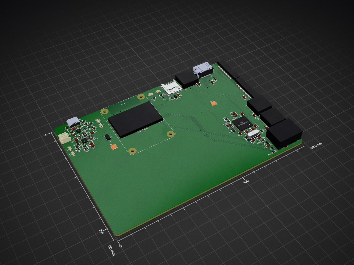
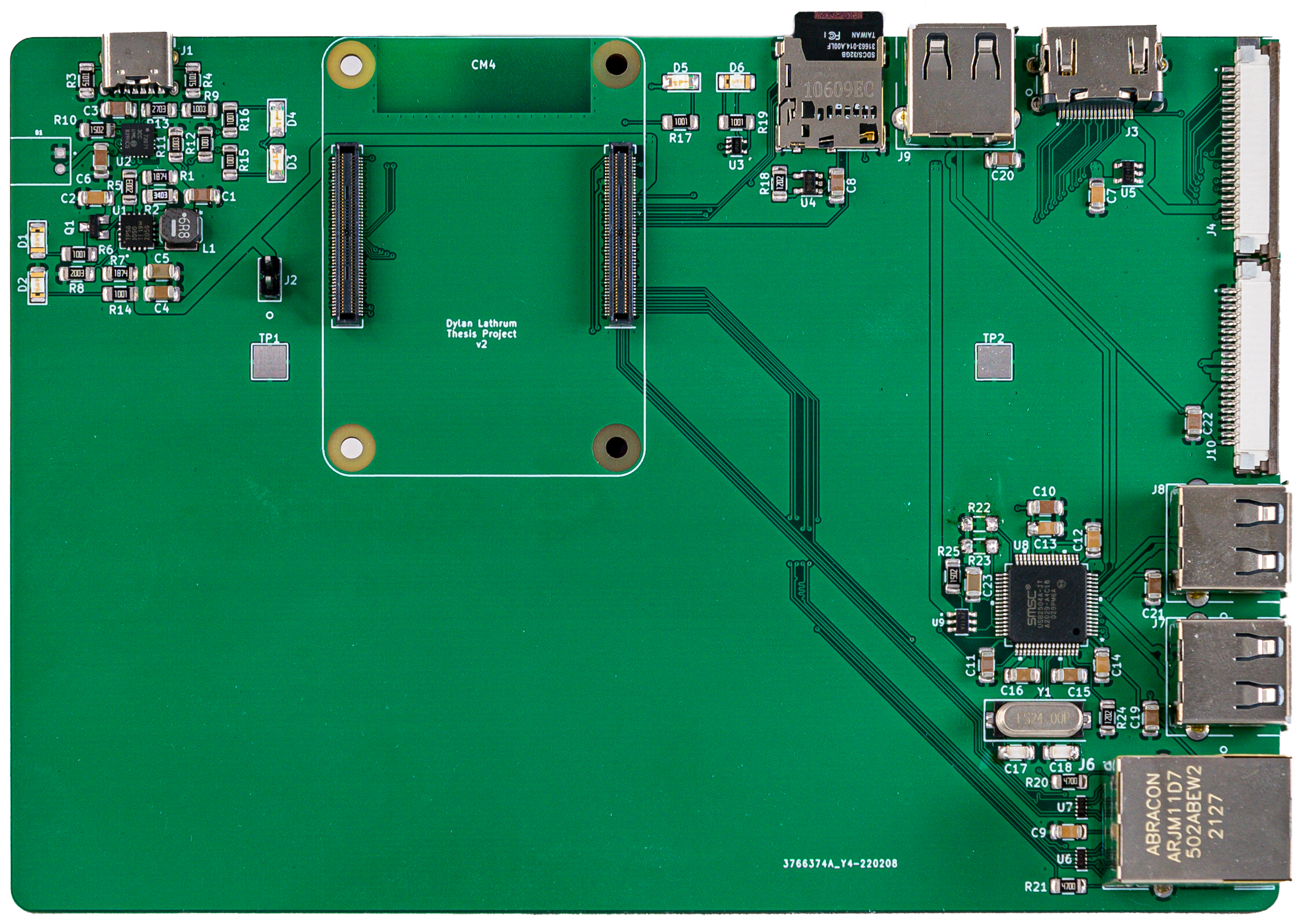
Lathrum thesis is an open-source printed circuit board by Dylancyclone, from the Dylancyclone/thesis repository on GitHub. It is a 2-layer board of 158.3 × 110 mm with 80 parts on 232 nets, routed with 1,460 tracks and 216 vias.
It is built around the 74LVC1G07, MCP73871-2CCI/ML and RT9742ENGJ5, with the RT9742VGJ5, USB2504A-JT and SS-52100-001 among its other parts. Its parts include 25 resistors, 23 capacitors, 10 connectors, 9 ICs and 6 diodes. It belongs with the Raspberry Pi (Linux) boards of this library.


(Alternatively, see it on asu.edu)
Watch a timelapse of the paper here: https://youtu.be/VJ2HCxnmA_Y
With the recent focus of attention towards remote work and mobile computing, the possibility of taking a powerful workstation wherever needed is enticing. However, even emerging laptops today struggle to compete with desktops in terms of cost, maintenance, and future upgrades. The price point of a powerful laptop is considerably higher compared to an equally powerful desktop computer, and most laptops are manufactured in a way that makes upgrading parts of the machine difficult or impossible, forcing a complete purchase in the event of failure or a component needing an upgrade.
In the case where someone already owns a desktop computer and must be mobile, instead of needing to purchase a second device at full price, it may be possible to develop a low-cost computer that has just enough power to connect to the existing desktop and run all processing there, using the mobile device only as a user interface.
This thesis will explore the development of a custom PCB that utilizes a Raspberry Pi Computer Module 4, as well as the development of a fork of the Open Source project Moonlight to stream a host machine's screen to a remote client. This implementation will be compared against other existing remote desktop solutions to analyze it's performance and quality.
This repository contains all the files and resources used to produce my Honors Thesis.
Folders are self-explanatory.
| Qty | Value | Footprint | References |
|---|---|---|---|
| 7 | 10u | Capacitor_SMD:C_1206_3216Metric_Pad1.33x1.80mm_HandSolder | C8, C10, C11, C19, C20, C21, C22 |
| 5 | 100n | Capacitor_SMD:C_1206_3216Metric_Pad1.33x1.80mm_HandSolder | C7, C9, C12, C13, C14 |
| 4 | 1k | Resistor_SMD:R_1206_3216Metric_Pad1.30x1.75mm_HandSolder | R6, R14, R17, R19 |
| 3 | 10uF | Capacitor_SMD:C_1206_3216Metric_Pad1.33x1.80mm_HandSolder | C1, C3, C6 |
| 3 | Red | LED_SMD:LED_1206_3216Metric_Pad1.42x1.75mm_HandSolder | D1, D2, D6 |
| 3 | SS-52100-001 | SS-52100-001:SS-52100-001 | J7, J8, J9 |
| 2 | 1.87M | Resistor_SMD:R_1206_3216Metric_Pad1.30x1.75mm_HandSolder | R1, R7 |
| 2 | 100k | Resistor_SMD:R_1206_3216Metric_Pad1.30x1.75mm_HandSolder | R9, R11 |
| 2 | 100uF | Capacitor_SMD:C_1206_3216Metric_Pad1.33x1.80mm_HandSolder | C5, C23 |
| 2 | 1K | Resistor_SMD:R_1206_3216Metric_Pad1.30x1.75mm_HandSolder | R15, R16 |
| 2 | 200k | Resistor_SMD:R_1206_3216Metric_Pad1.30x1.75mm_HandSolder | R5, R8 |
| 2 | 27pF | Capacitor_SMD:C_1206_3216Metric_Pad1.33x1.80mm_HandSolder | C17, C18 |
| 2 | 36K 1% | Resistor_SMD:R_1206_3216Metric_Pad1.30x1.75mm_HandSolder | R22, R23 |
| 2 | 4.7uF | Capacitor_SMD:C_1206_3216Metric_Pad1.33x1.80mm_HandSolder | C15, C16 |
| 2 | 470R | Resistor_SMD:R_1206_3216Metric_Pad1.30x1.75mm_HandSolder | R20, R21 |
| 2 | 5.1k | Resistor_SMD:R_1206_3216Metric_Pad1.30x1.75mm_HandSolder | R3, R4 |
| 2 | FFC3B07-20-T | FFC3B07-20-T:GCT_FFC3B07-20-T | J4, J10 |
| 2 | Green | LED_SMD:LED_1206_3216Metric_Pad1.42x1.75mm_HandSolder | D3, D5 |
| 2 | TPD4EUSB30 | Package_SON:USON-10_2.5x1.0mm_P0.5mm | U6, U7 |
| 2 | TestPoint | TestPoint:TestPoint_Pad_4.0x4.0mm | TP1, TP2 |
| 1 | 0.1uF | Capacitor_SMD:C_1206_3216Metric_Pad1.33x1.80mm_HandSolder | C2 |
| 1 | 1.0k | Resistor_SMD:R_1206_3216Metric_Pad1.30x1.75mm_HandSolder | R12 |
| 1 | 12K 1% | Resistor_SMD:R_1206_3216Metric_Pad1.30x1.75mm_HandSolder | R24 |
| 1 | 12k 1% | Resistor_SMD:R_1206_3216Metric_Pad1.30x1.75mm_HandSolder | R18 |
| 1 | 15K 1% | Resistor_SMD:R_1206_3216Metric_Pad1.30x1.75mm_HandSolder | R25 |
| 1 | 15k | Resistor_SMD:R_1206_3216Metric_Pad1.30x1.75mm_HandSolder | R10 |
| 1 | 2.2uF | Capacitor_SMD:C_1206_3216Metric_Pad1.33x1.80mm_HandSolder | C4 |
| 1 | 24MHz | Crystal:Crystal_SMD_HC49-SD | Y1 |
| 1 | 270k | Resistor_SMD:R_1206_3216Metric_Pad1.30x1.75mm_HandSolder | R13 |
| 1 | 340k | Resistor_SMD:R_1206_3216Metric_Pad1.30x1.75mm_HandSolder | R2 |
| 1 | 6.8uH | NRS5030T6R8MMGJ:NRS5030T6R8MMGJ | L1 |
| 1 | 74LVC1G07 | Package_TO_SOT_SMD:SOT-353_SC-70-5 | U3 |
| 1 | AP22653W6-7 | AP22653W6-7:SOT95P280X145-6N | U9 |
| 1 | ARJM11D7-502-AB-EW2 | ARJM11D7-502-AB-EW2:ARJM11D7502ABEW2 | J6 |
| 1 | ComputeModule4-CM4 | CM4IO:Raspberry-Pi-4-Compute-Module | CM4 |
| 1 | JST 2-PH | JST_S2B-PH-K-S(LF)(SN):JST_S2B-PH-K-S(LF)(SN) | B1 |
| 1 | MCP73871-2CCI_ML | digikey-footprints:QFN-20-1EP_4x4mm_RevA | U2 |
| 1 | MMUN2133LT1G | MMUN2133LT1G:SOT95P240X111-3N | Q1 |
| 1 | Micro_SD_Card_Det | CM4IO:SDCARD_MOLEX_503398-1892 | J5 |
| 1 | Orange | LED_SMD:LED_1206_3216Metric_Pad1.42x1.75mm_HandSolder | D4 |
| 1 | PREC002SAAN-RC | PREC002SAAN-RC:PREC002SAAN-RC | J2 |
| 1 | RT9742ENGJ5 | Package_TO_SOT_SMD:SOT-23-5 | U5 |
| 1 | RT9742VGJ5 | Package_TO_SOT_SMD:SOT-23-5 | U4 |
| 1 | SS-53000-001 | SS-53000-001:STEWART_SS-53000-001 | J3 |
| 1 | TPS61090RSAR | TPS61090RSAR:QFN65P400X400X100-17N | U1 |
| 1 | USB2504A-JT | USB2504A-JT:USB2504A-JT | U8 |
| 1 | USB4125-GF-A_REVA2 | USB4125-GF-A_REVA2:GCT_USB4125-GF-A_REVA2 | J1 |
It measures 158.3 × 110 mm and has 2 copper layers, 1.6 mm thick.
80 parts, built around the 74LVC1G07, MCP73871-2CCI/ML, RT9742ENGJ5 and RT9742VGJ5. The full list of its parts is on this page, with links to each part's symbol and footprint where PCBKit's library has them.
From the Dylancyclone/thesis repository on GitHub, at the commit this page was made from: the board is kicad/lathrum_thesis/lathrum_thesis.kicad_pcb and its schematic kicad/lathrum_thesis/cm4.kicad_sch. PCBKit opens the board in the browser, with nothing to install.
Its repository states no licence, so its author keeps all rights: ask Dylancyclone before reusing the design.


benkrasnow/1v2-boost-converter
Schematics and PCB layout for a boost converter 0.9V minimum input, 30A maximum input current


jrowe88/ecoport-bridge
CTA-2045 (EcoPort) bridge for a Rinnai REHP65 heat pump water heater
