4 layers160 × 100 mm
V2.1 board ecar isolated
Jonny999999/electric-kart
Firmware and pcb's for custom built electric kart
116 parts

 dustpot/electronic-test-bench
A Raspberry Pi 4 bench instrument featuring a function generator, ohmmeter, voltmeter, DC voltage reference, and frequency meter, all controlled with a rotary encoder and a 20×4 LCD.
Group4 CheckpointA KiCad 4-20-26 is an open-source printed circuit board by dustpot, from the dustpot/electronic-test-bench repository on GitHub. It is a 2-layer board of 207 × 146 mm with 103 parts on 127 nets, routed with 523 tracks and 22 vias.
It is built around the TL081, TL084CN and LM339N, with the IRF4905 and IRFZ24N among its other parts. Its parts include 63 resistors, 13 ICs, 11 capacitors, 10 connectors and 4 diodes. It belongs with the lEDs and displays boards of this library.


A Raspberry Pi 4 bench instrument built for ECSE 2920 (Design Methodology) at the University of Georgia, Spring 2026. It includes a function generator, ohmmeter, voltmeter, DC voltage reference, and frequency meter, all controlled with a rotary encoder and a 20×4 LCD.
This was a five-person team project. Original course repository: Herring-UGAECSE-2920-S26/Group-4
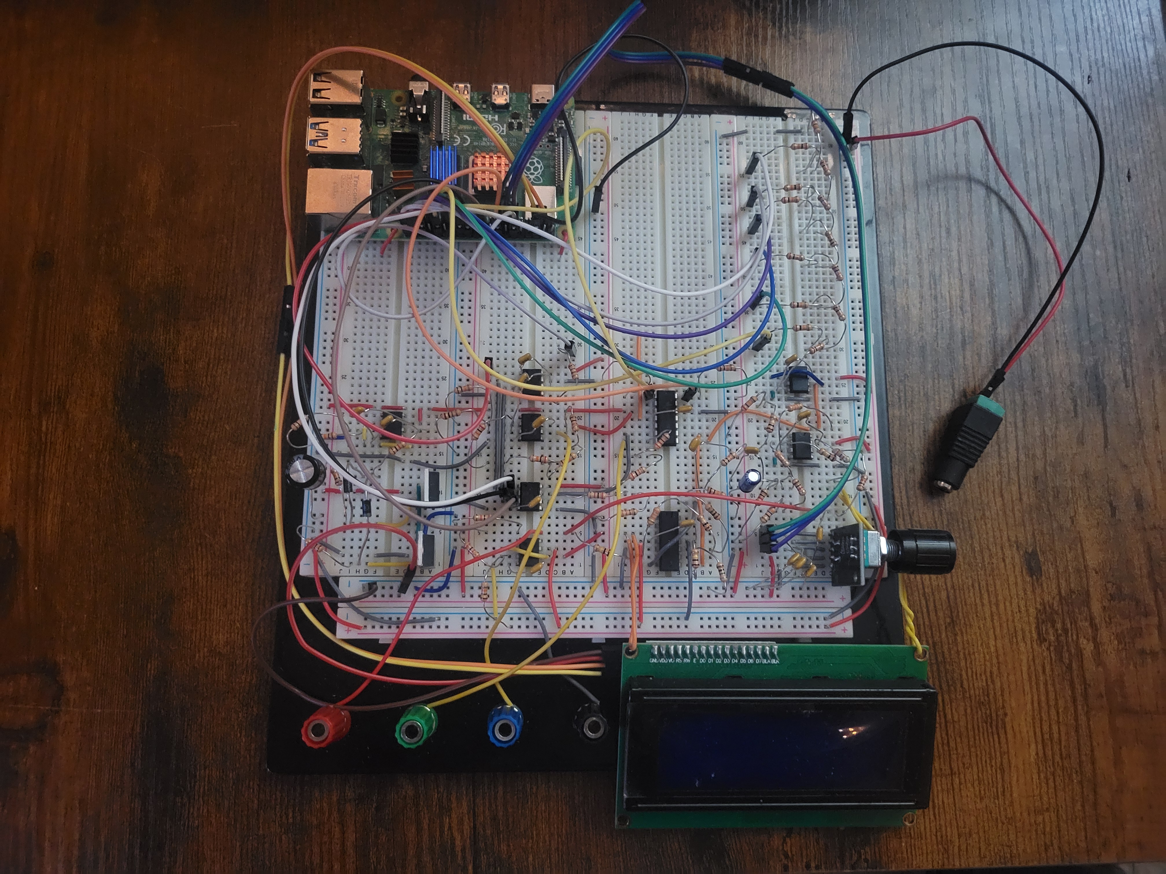
| Instrument | Range | How it works |
|---|---|---|
| Square wave | 100 Hz – 10 kHz | Pi hardware PWM (GPIO18) → MCP4131 digipot → TL084 amplifier |
| Sine wave | 1 – 10 kHz, 0 – 10 Vpp | DMA-timed PWM (GPIO13) → two RC low-pass filters → digipot → amplifier → DC offset stage |
| Ohmmeter | 500 Ω – 10 kΩ | Wheatstone bridge with an MCP4131 as the adjustable arm, LM339 comparator, 7-step binary search |
| Voltmeter | ±5 V | 6-bit SAR ADC (R-2R ladder + LM339), 5-reading majority vote per bit |
| DC reference | ±5 V | 6-bit R-2R ladder → TL084 level-shift and gain stage |
| Frequency meter | 1 – 10 kHz | LM339 comparator with hysteresis → GPIO24, rising-edge timestamps with pigpio |
| Power | 24 V in, ±12 V out | Virtual ground at 12 V, op-amp-driven MOSFET push-pull stage |
The user interface is a menu state machine driven entirely by a KY-040 rotary encoder (turn to move, press to select).
Measured during Checkpoint B testing.
| Instrument | Result |
|---|---|
| Ohmmeter | 5.5% average error across 10 resistors, 220 Ω – 10 kΩ |
| Square wave | Frequency within 0.04% of target, 100 Hz – 10 kHz |
| Voltmeter | Within 0.25 V of the source, −5 V to +5 V |
| DC reference | Within 0.1 V of the setpoint, −5 V to +3.1 V |
electronic-test-bench/
├── README.md
├── software/
│   ├── checkA_main.py
│   ├── adc.py
│   ├── digipot_dual.py
│   ├── freq_measure.py
│   ├── inputs.py
│   ├── lcd.py
│   └── requirements.txt
├── hardware/
│   ├── kicad/              # .kicad_pro, .kicad_sch, .kicad_pcb
│   └── schematics/         # PDF export of each subsystem
├── data/                   # calibration and test measurements (.csv)
└── docs/
    ├── ETB_Technical_Documentation.pdf
└── images/Requires a Raspberry Pi 4 with Python 3, SPI and I²C enabled.
sudo pigpiod
pip install -r software/requirements.txt
python3 software/checkA_main.pyFull design writeup: docs/ETB_Technical_Documentation.pdf
User manual: docs/User Manual.pdf
Avery Dedjoe, Allan Gramajo, Justin Park, Samuel Baker, Jakob Braski
| Qty | Value | Footprint | References |
|---|---|---|---|
| 23 | 10k | Resistor_THT:R_Axial_DIN0207_L6.3mm_D2.5mm_P2.54mm_Vertical | R2, R3, R4, R5, R18, R19, R20, R23, R29, R40, R42, R44, R47, R48, R56, R57 +7 |
| 7 | 20k | Resistor_THT:R_Axial_DIN0207_L6.3mm_D2.5mm_P2.54mm_Vertical | R1, R12, R13, R14, R15, R16, R17 |
| 6 | 1M | Resistor_THT:R_Axial_DIN0207_L6.3mm_D2.5mm_P2.54mm_Vertical | R10, R11, R31, R50, R55, R60 |
| 6 | Conn_01x02 | Connector_PinHeader_2.54mm:PinHeader_1x02_P2.54mm_Vertical | J1, J3, J6, J7, J9, J10 |
| 5 | 100k | Resistor_THT:R_Axial_DIN0207_L6.3mm_D2.5mm_P2.54mm_Vertical | R25, R27, R28, R53, R54 |
| 5 | TL081 | Package_DIP:DIP-8_W7.62mm | U8, U9, U11, U12, U14 |
| 4 | 1N4001 | Diode_THT:D_DO-41_SOD81_P10.16mm_Horizontal | D1, D2, D3, D4 |
| 3 | 0.1uF | Capacitor_THT:C_Disc_D5.0mm_W2.5mm_P2.50mm | C1, C3, C9 |
| 3 | 1k | Resistor_THT:R_Axial_DIN0207_L6.3mm_D2.5mm_P2.54mm_Vertical | R21, R33, R38 |
| 3 | 33k | Resistor_THT:R_Axial_DIN0207_L6.3mm_D2.5mm_P2.54mm_Vertical | R34, R35, R45 |
| 3 | Conn_01x01 | Connector_PinHeader_2.54mm:PinHeader_1x01_P2.54mm_Vertical | J4, J5, J8 |
| 3 | MCP4131-xxxx-P | Package_DIP:DIP-8_W7.62mm | U5, U7, U10 |
| 3 | TL071 | Package_DIP:DIP-8_W7.62mm | U1, U4, U6 |
| 2 | .1u | Capacitor_THT:C_Disc_D5.0mm_W2.5mm_P2.50mm | C10, C11 |
| 2 | .1u | Capacitor_THT:C_Disc_D5.0mm_W2.5mm_P5.00mm | C6, C8 |
| 2 | 1.1k | Resistor_THT:R_Axial_DIN0207_L6.3mm_D2.5mm_P2.54mm_Vertical | R26, R30 |
| 2 | 127k | Resistor_THT:R_Axial_DIN0207_L6.3mm_D2.5mm_P2.54mm_Vertical | R36, R37 |
| 2 | 2.2k | Resistor_THT:R_Axial_DIN0207_L6.3mm_D2.5mm_P2.54mm_Vertical | R22, R24 |
| 2 | 51k | Resistor_THT:R_Axial_DIN0207_L6.3mm_D2.5mm_P2.54mm_Vertical | R41, R49 |
| 1 | 1.37k | Resistor_THT:R_Axial_DIN0207_L6.3mm_D2.5mm_P2.54mm_Vertical | R32 |
| 1 | 100 | Resistor_THT:R_Axial_DIN0207_L6.3mm_D2.5mm_P2.54mm_Vertical | R39 |
| 1 | 10n | Capacitor_THT:C_Disc_D5.0mm_W2.5mm_P2.50mm | C5 |
| 1 | 10n | Capacitor_THT:C_Disc_D5.0mm_W2.5mm_P5.00mm | C7 |
| 1 | 1u | Capacitor_THT:CP_Radial_D10.0mm_P5.00mm | C4 |
| 1 | 220k | Resistor_THT:R_Axial_DIN0207_L6.3mm_D2.5mm_P2.54mm_Vertical | R51 |
| 1 | 2k | Resistor_THT:R_Axial_DIN0207_L6.3mm_D2.5mm_P2.54mm_Vertical | R46 |
| 1 | 3.6k | Resistor_THT:R_Axial_DIN0207_L6.3mm_D2.5mm_P2.54mm_Vertical | R43 |
| 1 | 38k | Resistor_THT:R_Axial_DIN0207_L6.3mm_D2.5mm_P2.54mm_Vertical | R63 |
| 1 | 39k | Resistor_THT:R_Axial_DIN0207_L6.3mm_D2.5mm_P2.54mm_Vertical | R52 |
| 1 | 4.7k | Resistor_THT:R_Axial_DIN0207_L6.3mm_D2.5mm_P2.54mm_Vertical | R58 |
| 1 | 470u | Capacitor_THT:CP_Radial_D10.0mm_P5.00mm | C2 |
| 1 | IRF4905 | Package_TO_SOT_THT:TO-220-3_Vertical | Q1 |
| 1 | IRFZ24N | Package_TO_SOT_THT:TO-220-3_Vertical | Q2 |
| 1 | LM339N | Package_DIP:DIP-14_W7.62mm | U2 |
| 1 | PiHeaderM | Connector_PinHeader_2.54mm:PinHeader_2x20_P2.54mm_Vertical | J2 |
| 1 | TL084CN | Package_DIP:DIP-14_W7.62mm | U3 |
Jonny999999/electric-kart
Firmware and pcb's for custom built electric kart

Jonny999999/valveToggler
Small analog controller PCB that drives a **5/3 pneumatic valve (2 coils)** to shake dust filters of a wood-chip extraction system.


phpkadir/KiCad-Sensorless-BLDC-ESC
I designed this pcb because I want to be able to try different microcontrollers as part of Electronic Speed Controller projects.


LewisHall123/Drone-controller-sleeve-PCB
A circuit designed to send commands to a drone that it controls. The inputs to the circuit that determine the commands sent come from six separate tribo-electric nanogenerators (TENG).

michaeltomdean/TENG-Drone-Control
Remote control drone project using triboelectric nanogenerators as human-machine interface sensors.

0hasant/Liion_Cell_Simulator
Single-cell characterization bench for 18650 and 21700 Li-ion cells (DMEGC INR45E, generic 3.5 Ah 18650). Part of the Solaris final-year project.
It measures 207 × 146 mm and has 2 copper layers, 1.6 mm thick.
103 parts, built around the TL081, TL084CN, LM339N and IRF4905. The full list of its parts is on this page, with links to each part's symbol and footprint where PCBKit's library has them.
From the dustpot/electronic-test-bench repository on GitHub, at the commit this page was made from: the board is hardware/kicad/Group4_CheckpointA_KiCad_4-20-26.kicad_pcb and its schematic hardware/kicad/DC Reference.kicad_sch. PCBKit opens the board in the browser, with nothing to install.
Its repository states no licence, so its author keeps all rights: ask dustpot before reusing the design.