12 layers280 × 111.2 mm
Fpga candelabra
chipsalliance/rocket-pcb
PCB libraries and templates for rocket-chip based FPGA/ASIC designs
738 parts21Apache-2.0

 dunkelstern/zerosensor
Raspberry Pi Zero sensor board
Zerosensor is an open-source printed circuit board by dunkelstern, from the dunkelstern/zerosensor repository on GitHub. It is a 2-layer board of 42.2 × 65 mm with 76 parts on 80 nets, routed with 739 tracks and 86 vias.
It is built around the LSF0108PW, 24LC32A/P and BC848. Its parts include 23 resistors, 9 capacitors, 6 ICs, 6 diodes and 2 transistors. It belongs with the sensors and measurement boards and the Raspberry Pi (Linux) boards of this library.


This work is licensed under a Creative Commons Attribution-ShareAlike 4.0 International License.
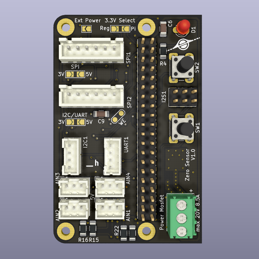
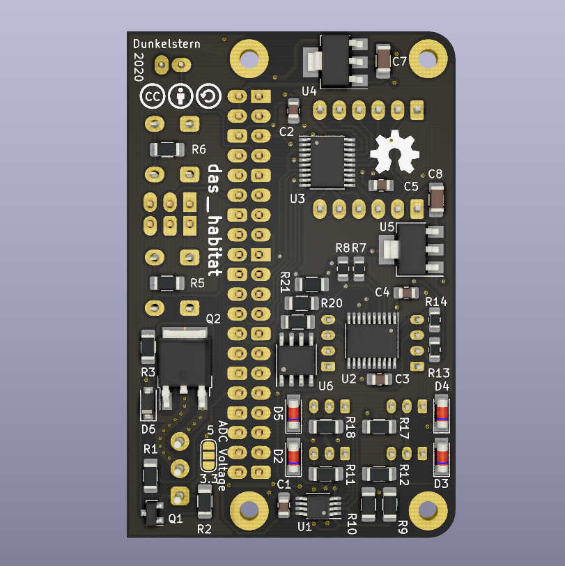
Please read this document before use, you have to set some solder jumpers to use the board!
gerber sub-directorysvg (be aware: this PCB has 86 vias and all through holes are supposed to be plated through!)assemblyassembly tooThere are 2 SPI ports broken out, they share MISO, MOSI and SCK lines and the chip enable pins of the Raspberry PI (CE0 and CE1) are split between the ports. I used bigger connectors here to differenciate the Ports from the smaller I2C and UART ports.
You have to select the voltage level on these ports by bridging the "SPI" solder jumper to the desired voltage.
The I2C port is Stemma/Grove/Quiic compatible. All lines are level-translated to the voltage selected with the "I2C/UART" solder jumper.
The UART is connected to the first UART of the Raspberry Pi, usually you get a debug console
on that port, but you can use it for other things too, you just have to disable the Getty
process on the UART. The UART shares the voltage selection with the I2C port, so if you need
power from the UART socket you'll have to bridge that solder jumper to the correct voltage.
The PCB footprint has been modified to accept any chips from the MAX116xx-Series. You can use any SOIC8 or SOT23-8 chip from the series, both will fit the board. The power supply for the chip is configurable via solder jumper "ADC Voltage" (3.3V or 5V) on the back side of the PCB.
The analog inputs are clamped to 3.6V with Zener diodes to avoid bricking the ADC when connecting something wrong or using long cables and getting voltage spikes.
Attention: Modify values of the voltage dividers accordingly!
R22/23 (1k and 1.8k) are calculated for 5V, leave R23 open and replace R22 with zero Ohm link for 3.3V supply.
Select the voltage divider for the inputs based on the reference voltage of the used ADC chip:
Group A is R11, R12, R17, R18, group B is R9, R10, R15, R16.
I2S is a digital audio bus, it can support two channels and up to 48kHz samplerate. This port has been broken out for use with an I2S MEMS microphone. It supports only 3.3V.
Two buttons on GPIO ports 22 and 23 are supplied. They have pull-up resistors on board, so the read level is inverse: GPIO high = button not pressed!
The LED is on GPIO port 4, use a low power LED here, the resistor is calculated for 15 mA.
The Power MOSFET is a P-Channel mosfet with a NPN transistor for voltage amplification. The PCB traces are laid out for 8.5A (thermal limit! traces will heat up to 60 degrees Celsius with that amount of power) but the MOSFET may switch 35A maximum (add cooling!). Be aware the Terminal block might be the limiting factor as it is only specified for 5A continous load.
The NPN transistor as well as the optional LDO (see below) can only handle 20V so be aware to not connect anything above that.
There is a small reverse clamping diode (max. 4A) if you want to switch a small inductive load like a relay.
The Power MOSFET Terminal block may be used to power the Raspberry Pi, for more information see below.
If you can not power the Raspberry Pi from an USB power supply you can install the 5V LDO (U4, C6, C7) and bridge the "Ext Power" solder jumper to "reverse"-power the PI from the Power MOSFET terminal block.
Attention: The LDO can only handle up to 1A of current (it will get hot in that case!) and a maximum of 20V. The minimum voltage to supply to run stable is about 6.5V.
The Raspberry Pi will use 250mA of the 1A power budget, so you have approximately 700mA to power your sensors and actuators.
If you want to isolate your sensors/actuators from the Raspberry Pi 3.3V power rail to avoid putting garbage on those voltage rails (probably crashing the Pi) or if you need a clean supply that is not influenced by the Pi that much you can add the 3.3V LDO (Parts U5, C8, C9) and bridge the "3.3V Select" solder jumber to "Reg" to use that regulator instead of the one on the Raspberry Pi board.
If you want to use the internal regulator of the Pi, bridge this jumper to "Pi", else you will not have any 3.3V supply on the board and no port will be functioning as the Level-shifters and the ADC will use the 3.3V supply.
The LDO has a capacity of 1A, but you will not be able to use that much power neither from the Pi (250mA will be used by the Pi itself, ca 700mA are available) nor from the external LDO (this depends on the 5V supply, if you're using External Power the 3.3V LDO is behind the 5V LDO, so both share the 700mA that are available from that, if you're using USB power it depends on what that power source is capable of).
There is an optional Hat EEPROM for autoconfiguration on the I2C0 bus of the Raspberry Pi, on boot the Pi reads the contents of that EEPROM chip to pre-configure the GPIO header and load drivers.
If you want to use this you'll have to program the EEPROM using the Raspberry Pi itself. On top of the PCB you can see two test-points with the letters "WR" beside them. If you bridge those the EEPROM will get writeable. You'll just have to activate the I2C0 bus and use the Raspberry Pi Hat utilities to create a ROM image for the chip.
| Qty | Value | Footprint | References |
|---|---|---|---|
| 5 | 100n | Capacitor_SMD:C_0805_2012Metric_Pad1.18x1.45mm_HandSolder | C1, C2, C3, C4, C5 |
| 4 | 1.5k | Resistor_SMD:R_0805_2012Metric_Pad1.20x1.40mm_HandSolder | R7, R8, R13, R14 |
| 4 | 10u | Capacitor_SMD:C_1206_3216Metric_Pad1.33x1.80mm_HandSolder | C6, C7, C8, C9 |
| 4 | 3.6V | Diode_SMD:D_MiniMELF | D2, D3, D4, D5 |
| 4 | a | Resistor_SMD:R_1206_3216Metric_Pad1.30x1.75mm_HandSolder | R11, R12, R17, R18 |
| 4 | b | Resistor_SMD:R_1206_3216Metric_Pad1.30x1.75mm_HandSolder | R9, R10, R15, R16 |
| 3 | 10k | Resistor_SMD:R_1206_3216Metric_Pad1.30x1.75mm_HandSolder | R3, R5, R6 |
| 2 | 1k | Resistor_SMD:R_1206_3216Metric_Pad1.30x1.75mm_HandSolder | R21, R22 |
| 2 | 3.9k | Resistor_SMD:R_1206_3216Metric_Pad1.30x1.75mm_HandSolder | R19, R20 |
| 2 | LSF0108 | Package_SO:TSSOP-20_4.4x6.5mm_P0.65mm | U2, U3 |
| 2 | SW_Push | Button_Switch_THT:SW_PUSH_6mm_H13mm | SW1, SW2 |
| 1 | 1.8k | Resistor_SMD:R_1206_3216Metric_Pad1.30x1.75mm_HandSolder | R23 |
| 1 | 24LC32 | Package_SO:SOIC-8_3.9x4.9mm_P1.27mm | U6 |
| 1 | 3.3V Select | Jumper:SolderJumper-3_P2.0mm_Open_TrianglePad1.0x1.5mm_NumberLabels | JP4 |
| 1 | 4.7k | Resistor_SMD:R_1206_3216Metric_Pad1.30x1.75mm_HandSolder | R2 |
| 1 | 470 | Resistor_SMD:R_1206_3216Metric_Pad1.30x1.75mm_HandSolder | R1 |
| 1 | 91 | Resistor_SMD:R_1206_3216Metric_Pad1.30x1.75mm_HandSolder | R4 |
| 1 | ADC Voltage | Jumper:SolderJumper-3_P1.3mm_Open_RoundedPad1.0x1.5mm_NumberLabels | JP5 |
| 1 | AIN1 | Connector_JST:JST_PH_B3B-PH-K_1x03_P2.00mm_Vertical | AIN1 |
| 1 | AIN2 | Connector_JST:JST_PH_B3B-PH-K_1x03_P2.00mm_Vertical | AIN2 |
| 1 | AIN3 | Connector_JST:JST_PH_B3B-PH-K_1x03_P2.00mm_Vertical | AIN3 |
| 1 | AIN4 | Connector_JST:JST_PH_B3B-PH-K_1x03_P2.00mm_Vertical | AIN4 |
| 1 | AO D4185 | Package_TO_SOT_SMD:TO-252-2 | Q2 |
| 1 | BAT43W-V | Diode_SMD:D_SOD-123 | D6 |
| 1 | BC848 | Package_TO_SOT_SMD:SOT-23 | Q1 |
| 1 | I2C | Connector_JST:JST_PH_B4B-PH-K_1x04_P2.00mm_Vertical | I2C1 |
| 1 | I2C UART Volt | Jumper:SolderJumper-3_P2.0mm_Open_TrianglePad1.0x1.5mm_NumberLabels | JP1 |
| 1 | I2S | Connector_PinHeader_2.54mm:PinHeader_2x03_P2.54mm_Vertical | I2S1 |
| 1 | LED | LED_THT:LED_D3.0mm | D1 |
| 1 | MAX116xx | Package_SO:MSOP-8_3x3mm_P0.65mm | U1 |
| 1 | NCP1117-3.3 | Package_TO_SOT_SMD:SOT-223-3_TabPin2 | U5 |
| 1 | NCP1117-5.0 | Package_TO_SOT_SMD:SOT-223-3_TabPin2 | U4 |
| 1 | Power In | Jumper:SolderJumper-2_P1.3mm_Open_TrianglePad1.0x1.5mm | JP2 |
| 1 | Raspberry_Pi_2_3 | Connector_PinHeader_2.54mm:PinHeader_2x20_P2.54mm_Vertical | J2 |
| 1 | SPI Volt | Jumper:SolderJumper-3_P2.0mm_Open_TrianglePad1.0x1.5mm_NumberLabels | JP3 |
| 1 | SPI1 | Connector_JST:JST_XH_B6B-XH-A_1x06_P2.50mm_Vertical | SPI1 |
| 1 | SPI2 | Connector_JST:JST_XH_B6B-XH-A_1x06_P2.50mm_Vertical | SPI2 |
| 1 | Strobe | TerminalBlock_Phoenix:TerminalBlock_Phoenix_PT-1,5-3-3.5-H_1x03_P3.50mm_Horizontal | J5 |
| 1 | UART | Connector_JST:JST_PH_B4B-PH-K_1x04_P2.00mm_Vertical | UART1 |
| 1 | Write | TestPoint:TestPoint_2Pads_Pitch2.54mm_Drill0.8mm | TP1 |
The 65 most common of 76 parts.
It measures 42.2 × 65 mm and has 2 copper layers, 1.6 mm thick.
76 parts, built around the LSF0108PW, 24LC32A/P and BC848. The full list of its parts is on this page, with links to each part's symbol and footprint where PCBKit's library has them.
From the dunkelstern/zerosensor repository on GitHub, at the commit this page was made from: the board is zerosensor.kicad_pcb. PCBKit opens the board in the browser, with nothing to install.
Its repository states no licence, so its author keeps all rights: ask dunkelstern before reusing the design.
chipsalliance/rocket-pcb
PCB libraries and templates for rocket-chip based FPGA/ASIC designs

mschwingen/hardware
Hardware designs by Michael Schwingen, michael at schwingen dot org

biomimetics/MRIRobot_PCB
PC boards for MRI robogt control, specifically for STM32 motherboard

coco-chameleon/chameleon-hardware
TRS-80 Color Computer cartridge emulator


dunkelstern/planticam-sensor-block
Planticam Sensor addon-board to allow sensing with 1 Wire and analog sensors and switching external loads

blazer82/gb.fpga
FPGA-based handheld console that plays games from Gameboy cartridges

peterkrull/quad
Firmware, hardware and documentation for my autonomous quad copter project