2 layers56.2 × 68.2 mm
Flexcable fab
dsi-modchip/pcb
This repository contains the KiCAD design files for the DSi modchip and the cable flex-PCB.
15 parts2CERN-OHL-S-2.0
 dsi-modchip/pcb2
This repository contains the KiCAD design files for the DSi modchip and the cable flex-PCB.
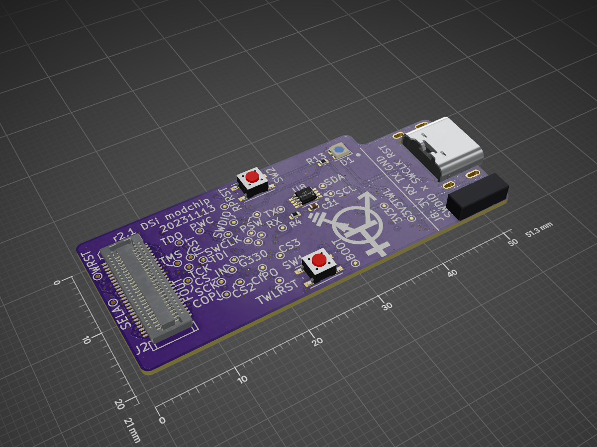
Wifi interposer is an open-source printed circuit board by dsi-modchip, from the dsi-modchip/pcb repository on GitHub, published under the CERN-OHL-S-2.0 licence. It is a 4-layer board of 51.3 × 21 mm with 89 parts on 95 nets, routed with 922 tracks and 188 vias.
It is built around the RP2040, W25Q16JVUXIQ and D1213A-02SM, with the MIC5317-1.8YD5-TR, PCA9306DC1 and USBLC6-2SC6 among its other parts. Its parts include 20 capacitors, 13 resistors, 8 ICs, 5 connectors and 2 switches. It belongs with the radio and wireless boards and the RP2040 boards of this library.


[!IMPORTANT] This PCB is still a work-in-progress and has bugs.
This repository contains the KiCAD design files for the DSi modchip and the cable flex-PCB.
Currently, you'll have to order and make these yourself. I don't think making them widely available already is a good idea, there's still a few bugs left in the design.
The issues with the modchip PCB itself are listed here. Additionally, inserting a cable into the modchips USB socket too forcefully can cause the modchip PCB to snap in half, which is bad.
I haven't actually gotten the flex-cable to work properly. There are problems with either a too large parasitic capacitance on the glitch signal line, or bad contacts between the flexPCB and the glitching MOSFET. I suggest deadbugging the crowbar MOSFET instead, if that's something you're capable of.
The modchip is a 4-layer board that should be 0.8 mm thick. I've gotten it fabbed successfully from both Aisler (at 1.6mm thickness) and JLCPCB.
The flex-cable consists of two layers, needs stiffner in certain places, and has been fabbed from JLCPCB.
These are all the components required for the core functionality of the modchip.
| Reference | Value | Footprint | Qty | Farnell n° | LCSC n° | Mouser n° |
|---|---|---|---|---|---|---|
| C3,C4 | 27pF C0G | 0402 | 2 | 4539081 | C880615 | 603-CC402GRNPO9BN270 |
| C5,C6,C7,C10,C11,C12,C13,C14,C15,C16,C17 | 100nF | 0402 | 11 | 1758880 | C16772 | 791-0402B224K100CT |
| C8,C9 | 1uF | 0402 | 2 | 3013332 | C12530 | 187-CL05A105KP5NNNC |
| J1 | Molex SlimStack 501920-5001 | 1 | N/A | N/A | 538-501920-5001 | |
| J5 | Molex 200528-0040 | 1 | 3500399 | N/A | 538-200528-0040 | |
| Q4 | Dual NPMOS | SOT-363/SC-70-6 | 1 | 3828400 | C155499 | 621-DMC3400SDW-13 |
| R1,R2 | 10k | 0402 | 2 | 2787800 | C25744 | 279-CRG0402J10K/10 |
| R5 | 47k | 0402 | 2 | 4004532 | C25792 | 279-CRG0402J47K |
| R7,R8 | 1k | 0402 | 2 | 4004531 | C11702 | 603-RC0402FR-131KL |
| SW1, SW2 | 1P1T button | 4.2x3.2mm | 2 | 3703693 | C2689510 | 611-RKB2SJM250SMTRLF |
| U1 | RP2040 | QFN-56 P0.4 | 1 | 3766082 | C2040 | 358-SC09147 |
| U2,U4 | W25Q16JVUXIQ | DFN-8 P0.5mm | 2 | N/A | C2983691 | 454-W25Q16JVUXIQTR |
| Y2 | 12 MHz 18pF | SMD3225 GND2/4 | 1 | 3572992 | C7424717 | 774-403C35D12M00000 |
[!NOTE]
J5is optional, and is only needed when you use the flex-cable. It can be omitted when deadbugging the crowbar MOSFET.
[!TIP]
- For Q4, several compatible components exist: Diodes DMC{2710U,3400S,3401L}DW, Toshiba SSM6L35FU.
- For SW1 and SW2, you can use one of the following:
- C&K {RKB,PTS81[05]}2SJ[GKM]250SMTR LF
- Alps Alpine SKRPABE010
- E-Switch TL3365AF180QG
- CUI TS20-42-25-WT-160-SMT-TR
- Wurth 434123025826 or 434133025816
- For U1, you could try using the RP2350A once its erratum E9 has been fixed in hardware.
- For U2 and U4, any similarly-sized 3.3V >100MHz QSPI flash chip should work. Requirements on U4 are lower (only 1-bit SPI, 16 MHz) but it's often cheaper to buy the same chip in bulk.
- For Y2, try e.g. ECS-120-18-33 or ABM8(G)-12.000MHZ-18
[!IMPORTANT] You most likely want this, though technically everything can be done using an SWD debugger instead.
| Reference | Value | Footprint | Qty | Farnell n° | LCSC n° | Mouser n° |
|---|---|---|---|---|---|---|
| C1,C2 | 1uF | 0402 | 2 | 3013332 | C12530 | 187-CL05A105KP5NNNC |
| F1 | 0.5A | 0603 | 1 | 2850001 | C163116 | 530-C2Q500 |
| J3 | USBC 2.0 Recp | USBC 16P | 1 | 3819289 | C428463 | 640-USB4520031A |
| R3,R11 | 47k | 0402 | 2 | 4004532 | C25792 | 279-CRG0402J47K |
| R6,R12 | 5.1k | 0402 | 2 | 2447201 | C25905 | 708-RMCF0402FT5K10 |
| R9,R10 | 27 1% | 0402 | 2 | 4014781 | C100623 | 791-RMC1/16SK27R0FTH |
| U6 | AP2127K-3.3 | SOT-23-5 | 1 | 2510377 | C81233 | 998-MIC5504-3.3YM5TR |
| U3 | D1213A-02SM | SOT-23-5 | 1 | 3946109 | N/A | 621-D1213A-02SM-7 |
| U7 | USBLC6-2SC6 | SOT-23-6 | 1 | 1269406 | C2827654 | 511-USBLC6-2SC6 |
[!IMPORTANT] Use only one of
U3orU7, never both!
It indicates the status, except it doesn't work because there's no proper 5V rail available when plugged into the DSi.
| Reference | Value | Footprint | Qty | Farnell n° | LCSC n° | Mouser n° |
|---|---|---|---|---|---|---|
| D1 | WS2812B | PLCC-2020 | 1 | N/A | C965555 | 485-4684 |
| R13 | 330 | 0402 | 1 | TODO | TODO | TODO |
With a few extra components, you can make the modchip act as a real interposer PCB between the DSi motherboard and the WiFi module.
| Reference | Value | Footprint | Qty | Farnell n° | LCSC n° | Mouser n° |
|---|---|---|---|---|---|---|
| C18,C19 | 1uF | 0402 | 2 | 3013332 | C12530 | 187-CL05A105KP5NNNC |
| J2 | Molex SlimStack 52991-0508 | 1 | 3500613 | N/A | 538-52991-0508 | |
| U5 | MIC5317-1.8YD5 | SOT-23-5 | 1 | 2809977 | C236669 | 998-MIC5504-1.8YM5TR |
[!NOTE] Only short
JP1if you intend to talk to the WiFi module in a standalone (i.e. non-interposer) manner.
[!TIP] Instead of a MIC5317, many other SOT-23-5 LDOs such as the MIC5504-1.8YM5 can be used instead. I tend to pick ones with a low quiescent current. Do pay attention to the pinout, though, as it sometimes changes even between SOT-23-5 parts of the same vendor.
This can be a neat extra if you want to talk to the DSi's I2C bus. This was used during modchip development, but isn't required at runtime.
| Reference | Value | Footprint | Qty | Farnell n° | LCSC n° | Mouser n° |
|---|---|---|---|---|---|---|
| C21 | 100nF | 0402 | 1 | 1758880 | C16772 | 791-0402B224K100CT |
| R4 | 200k | 0402 | 1 | 3537789 | C25764 | 791-WR04X2003FTL |
| U8 | PCA9306DC1 | VSSOP-8 | 1 | 2400482 | C33196 | 595-PCA9306DCUR |
[!TIP] Instead of a PCA9306 (from either TI or NXP), an LSF0102 (from TI or Nexperia) or Nexperia NCA9306 can be used as well.
The flex-cable only needs a single IRFHS8342PbF as crowbar MOSFET. There's also a footprint for a small 0402 series resistance at the gate (e.g. 200 Ohm), but it can be shorted.
See the guide.
| Qty | Value | Footprint | References |
|---|---|---|---|
| 12 | 100nF | Capacitor_SMD:C_0402_1005Metric | C5, C6, C7, C10, C11, C12, C13, C14, C15, C16, C17, C21 |
| 6 | 1uF | Capacitor_SMD:C_0402_1005Metric | C1, C2, C8, C9, C18, C19 |
| 4 | GND | footprints:TestPoint_Circular_D0.5 | TP34, TP35, TP36, TP37 |
| 3 | 47k | Resistor_SMD:R_0402_1005Metric | R3, R5, R11 |
| 2 | 10k | Resistor_SMD:R_0402_1005Metric | R1, R2 |
| 2 | 1k | Resistor_SMD:R_0402_1005Metric | R7, R8 |
| 2 | 27 1% | Resistor_SMD:R_0402_1005Metric | R9, R10 |
| 2 | 27pF | Capacitor_SMD:C_0402_1005Metric | C3, C4 |
| 2 | 5.1k | Resistor_SMD:R_0402_1005Metric | R6, R12 |
| 2 | SW_Push | Button_Switch_SMD:SW_Push_1P1T_NO_Vertical_Wuerth_434133025816 | SW1, SW2 |
| 2 | W25Q16JVUXIQ | Package_DFN_QFN:DFN-8-1EP_3x2mm_P0.5mm_EP1.36x1.46mm | U2, U4 |
| 1 | 0.5A | Fuse:Fuse_0603_1608Metric | F1 |
| 1 | 12.000MHz | Crystal:Crystal_SMD_3225-4Pin_3.2x2.5mm | Y2 |
| 1 | 200k | Resistor_SMD:R_0402_1005Metric | R4 |
| 1 | 330 | Resistor_SMD:R_0402_1005Metric | R13 |
| 1 | 3V3 | footprints:TestPoint_Circular_D0.5 | TP19 |
| 1 | 3V3TWL | footprints:TestPoint_Circular_D0.5 | TP18 |
| 1 | AP2127K-3.3 | Package_TO_SOT_SMD:SOT-23-5 | U6 |
| 1 | BOOT | footprints:TestPoint_Circular_D0.5 | TP21 |
| 1 | CIPO | footprints:TestPoint_Circular_D0.5 | TP5 |
| 1 | COPI | footprints:TestPoint_Circular_D0.5 | TP4 |
| 1 | CS2 | footprints:TestPoint_Circular_D0.5 | TP7 |
| 1 | CS3 | footprints:TestPoint_Circular_D0.5 | TP8 |
| 1 | CS_IN | footprints:TestPoint_Circular_D0.5 | TP6 |
| 1 | D1213A-02SM | Package_TO_SOT_SMD:SOT-23-5 | U3 |
| 1 | FOUT | footprints:TestPoint_Circular_D0.5 | TP14 |
| 1 | G330 | footprints:TestPoint_Circular_D0.5 | TP32 |
| 1 | GND2 on CPU-TWL-01 PCB, TP14 on CPU-UTL-01 PCB | TestPoint:TestPoint_Pad_D2.0mm | TP2 |
| 1 | GlitchFPC | Connector_FFC-FPC:Molex_200528-0040_1x04-1MP_P1.00mm_Horizontal | J5 |
| 1 | MIC5317-1.8YD5 | Package_TO_SOT_SMD:SOT-23-5 | U5 |
| 1 | PCA9306DC1 | Package_SO:VSSOP-8_2.3x2mm_P0.5mm | U8 |
| 1 | PSW | footprints:TestPoint_Circular_D0.5 | TP38 |
| 1 | PWC | footprints:TestPoint_Circular_D0.5 | TP33 |
| 1 | Q_Dual_NPMOS_S1G1D2S2G2D1 | Package_TO_SOT_SMD:SOT-363_SC-70-6 | Q4 |
| 1 | RP2040 | Package_DFN_QFN:QFN-56-1EP_7x7mm_P0.4mm_EP3.2x3.2mm | U1 |
| 1 | RPRST | footprints:TestPoint_Circular_D0.5 | TP20 |
| 1 | RX | footprints:TestPoint_Circular_D0.5 | TP23 |
| 1 | SCK | footprints:TestPoint_Circular_D0.5 | TP3 |
| 1 | SCL | footprints:TestPoint_Circular_D0.5 | TP29 |
| 1 | SDA | footprints:TestPoint_Circular_D0.5 | TP30 |
| 1 | SELA | footprints:TestPoint_Circular_D0.5 | TP15 |
| 1 | SOICbite | footprints:SOIC_clipProgSmall | J8 |
| 1 | SWCLK | footprints:TestPoint_Circular_D0.5 | TP24 |
| 1 | SWDIO | footprints:TestPoint_Circular_D0.5 | TP25 |
| 1 | SolderJumper_2_Open | Jumper:SolderJumper-2_P1.3mm_Open_RoundedPad1.0x1.5mm | JP1 |
| 1 | TCK | footprints:TestPoint_Circular_D0.5 | TP12 |
| 1 | TDI | footprints:TestPoint_Circular_D0.5 | TP11 |
| 1 | TDO | footprints:TestPoint_Circular_D0.5 | TP9 |
| 1 | TMS | footprints:TestPoint_Circular_D0.5 | TP10 |
| 1 | TRST | footprints:TestPoint_Circular_D0.5 | TP13 |
| 1 | TWLRST | footprints:TestPoint_Circular_D0.5 | TP17 |
| 1 | TWL_WifiConn_Plug_TO_MAINBRD | footprints:Molex_SlimStack_501920-5001_2x25_P0.50mm_Vertical | J1 |
| 1 | TWL_WifiConn_Rcpt_TO_WIFIBRD | Connector_Molex:Molex_SlimStack_52991-0508_2x25_P0.50mm_Vertical | J2 |
| 1 | TX | footprints:TestPoint_Circular_D0.5 | TP22 |
| 1 | To glitch FET | TestPoint:TestPoint_Pad_D2.0mm | TP1 |
| 1 | USBLC6-2SC6 | Package_TO_SOT_SMD:SOT-23-6 | U7 |
| 1 | USB_C_Receptacle_USB2.0 | footprints:USB_C_Receptacle_GCT_USB4510 | J3 |
| 1 | WRST | footprints:TestPoint_Circular_D0.5 | TP16 |
| 1 | WS2812B | LED_SMD:LED_WS2812B-2020_PLCC4_2.0x2.0mm | D1 |
The 87 most common of 89 parts.
dsi-modchip/pcb
This repository contains the KiCAD design files for the DSi modchip and the cable flex-PCB.

dsi-modchip/pcb
This repository contains the KiCAD design files for the DSi modchip and the cable flex-PCB.

dsi-modchip/pcb
This repository contains the KiCAD design files for the DSi modchip and the cable flex-PCB.


immortal-sniper1/ESP32_power_meter_MP3_player_WIFI_radio
Fistst ESP and STM32 pcb project, it will have a power meter sd crd wifi and the ability to play back MP3 file (and maybe more) . Also it will feature a power usage meter. Maybe it will aso have battery power option


MoreThanRobotsFR/MTR_Tiny_MD
This Arduino project utilizes SimpleFOC library for sensor-based brushless motor control with a DRV8316 driver. It also incorporates an Adafruit NeoPixel for visual feedback.

nerdmaennchen/WattaVolt
this repository contains hardware + software for my custom PSU/bringup-tool/younameit


mymakercorner/Leyden_Jar
A modernized controller PCB for the Brand New Model F and Beam Spring keyboards

adammakesthingsdev/Orpheus-Pico-Kicad
Kicad files and JLCPCB production gerbers for Orpheus Pico
It measures 51.3 × 21 mm and has 4 copper layers, 0.8 mm thick.
89 parts, built around the RP2040, W25Q16JVUXIQ, D1213A-02SM and MIC5317-1.8YD5-TR. The full list of its parts is on this page, with links to each part's symbol and footprint where PCBKit's library has them.
From the dsi-modchip/pcb repository on GitHub, at the commit this page was made from: the board is wifi-interposer/wifi-interposer.kicad_pcb and its schematic flexcable/flexcable.kicad_sch. PCBKit opens the board in the browser, with nothing to install.
Its repository publishes it under the CERN-OHL-S-2.0 licence: you may reuse it on that licence's terms (keep the author's notice, and for a copyleft licence share your changes alike).