2 layers40 × 30 mm

 dsbaars/orangeclock-s-mini-adapter5
Source file for the adapter board, to make an OrangeClock out of a WeAct 2.9 inch display in combination with a S* mini.
Orangeclock adapter is an open-source printed circuit board by dsbaars, from the dsbaars/orangeclock-s-mini-adapter repository on GitHub, published under the GPL-3.0 licence. It is a 2-layer board of 34.8 × 30.2 mm with 3 parts on 31 nets, routed with 42 tracks and 0 vias.
It belongs with the interfaces and adapters boards of this library.
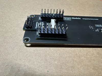
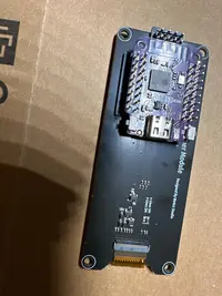
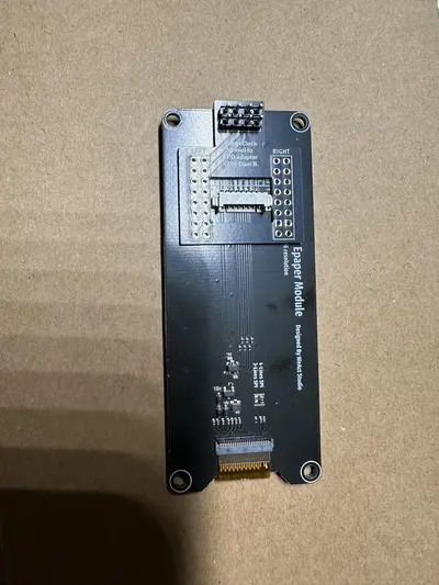
RST_PIN         = 3
DC_PIN          = 2
CS_PIN          = 4
BUSY_PIN = 1RST_PIN = 2
DC_PIN = 3
CS_PIN = 5
BUSY_PIN = 1| Qty | Value | Footprint | References |
|---|---|---|---|
| 1 | Conn_02x08_Odd_Even | Connector_PinHeader_2.54mm:PinHeader_2x08_P2.54mm_Vertical | LEFT |
| 1 | Conn_02x08_Odd_Even | Connector_PinHeader_2.54mm:PinHeader_2x08_P2.54mm_Vertical_nognd | RIGHT |
| 1 | EPD | Connector_PinHeader_2.54mm:PinHeader_2x04_P2.54mm_Vertical | J1 |
It measures 34.8 × 30.2 mm and has 2 copper layers, 1.6 mm thick.
3 parts. The full list of its parts is on this page, with links to each part's symbol and footprint where PCBKit's library has them.
From the dsbaars/orangeclock-s-mini-adapter repository on GitHub, at the commit this page was made from: the board is orangeclock-adapter/orangeclock-adapter.kicad_pcb and its schematic orangeclock-adapter/orangeclock-adapter.kicad_sch. PCBKit opens the board in the browser, with nothing to install.
Its repository publishes it under the GPL-3.0 licence: you may reuse it on that licence's terms (keep the author's notice, and for a copyleft licence share your changes alike).

hzeller/rpi-rgb-led-matrix
Controlling up to three chains of 64x64, 32x32, 16x32 or similar RGB LED displays using Raspberry Pi GPIO


atopile/atopile
Design circuit boards with code! ✨ Get software-like design reuse 🚀, validation, version control and collaboration in hardware; starting with electronics ⚡️


hackclub/sprig
🍃 Learn to code by making games in a JavaScript web-based game editor.