

2 layers80 × 110 mm
NucDeck Left Controller PCB
dmcke5/NucDeck
The Open Source DIY Handheld Gaming PC!
59 parts561CERN-OHL-S-2.0

 dsalaj/cybr_light_blade
Each blade carries 12 small 0805 LEDs and 6 glowing 38 mm LED filaments. Ten WS2811 driver chips control them, so the controller sees each blade as 10 standard RGB pixels.
Light blade is an open-source printed circuit board by dsalaj, from the dsalaj/cybr_light_blade repository on GitHub. It is a 2-layer board of 356 × 65 mm with 68 parts on 62 nets, routed with 255 tracks and 42 vias.
It is built around the WS2811. Its parts include 21 resistors, 18 diodes, 11 capacitors, 10 ICs and 2 connectors.
 ██╗     ██╗ ██████╗ ██╗  ██╗████████╗    ██████╗ ██╗      █████╗ ██████╗ ███████╗
 ██║     ██║██╔════╝ ██║  ██║╚══██╔══╝    ██╔══██╗██║     ██╔══██╗██╔══██╗██╔════╝
 ██║     ██║██║  ███╗███████║   ██║       ██████╔╝██║     ███████║██║  ██║█████╗
 ██║     ██║██║   ██║██╔══██║   ██║       ██╔══██╗██║     ██╔══██║██║  ██║██╔══╝
 ███████╗██║╚██████╔╝██║  ██║   ██║       ██████╔╝███████╗██║  ██║██████╔╝███████╗
 ╚══════╝╚═╝ ╚═════╝ ╚═╝  ╚═╝   ╚═╝       ╚═════╝ ╚══════╝╚═╝  ╚═╝╚═════╝ ╚══════╝
          >>  DIY_CYBERPUNK  //  LGHT_BLD  //  WS2811 PIXEL SWORD  <<



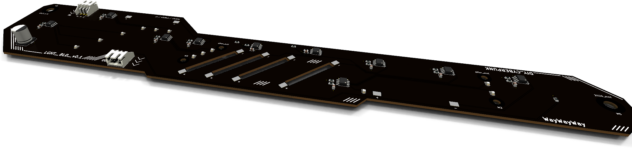
A 356 mm, sword-shaped, daisy-chainable LED board. It plugs into a WLED / Elite 4D-EXMU controller like an ordinary pixel strip.
> SYS.INFOEach blade carries 12 small 0805 LEDs and 6 glowing 38 mm LED filaments. Ten WS2811 driver chips control them, so the controller sees each blade as 10 standard RGB pixels. Chain as many blades as your power supply can feed: data comes in on IN and goes out on OUT, one blade after another.
PARAM | VALUE |
|---|---|
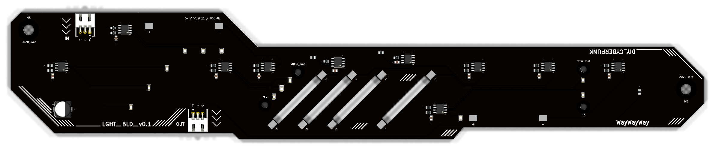
| Outline | 356 × 65 mm sword: hilt, 45° guard, slotted blade, bevelled tip |
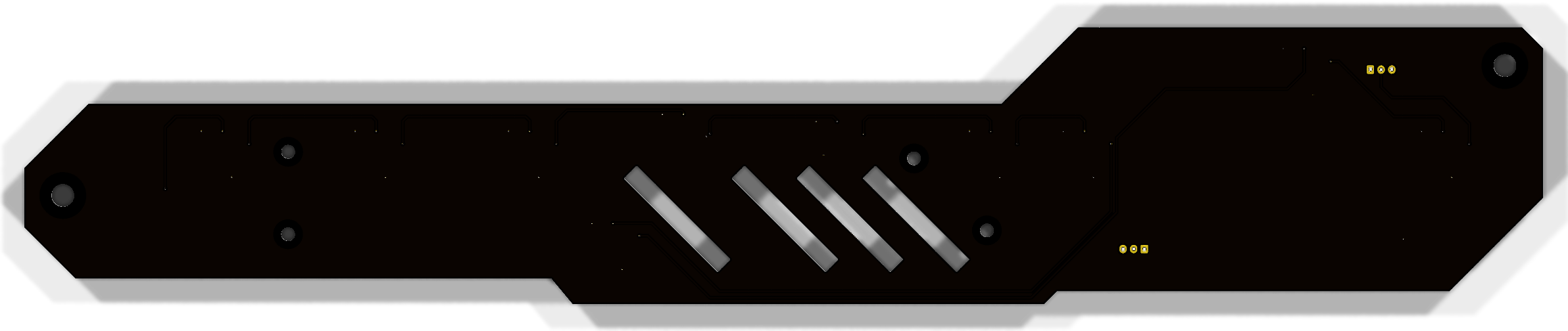
| Stackup | 2 layers, 1.6 mm, black soldermask, white silkscreen |
| Drivers | 10 × Worldsemi WS2811 (SOP-8), constant-current 18.5 mA outputs |
| Light | 12 × 0805 white LEDs + 6 × 3 V / 38 mm filaments |
| Protocol | WS281x single wire, 800 kHz (SET pin left floating) |
| Supply | 5 V, ≈ 0.58 A per blade at full white |
| I/O | 2 × JST XH 3-pin, right-angle (IN / OUT) |
| Mounting | 2 × M5 (2020 extrusion) + 4 × M3 (diffuser), copper-free keepouts |
> VISUAL.FEED[ TOP ]
[ BOTTOM ]: solid GND plane, with the data chain hopping along it
> PIXEL.MAPData flows chip to chip in this order. Each WS2811 is one pixel in WLED.
flowchart LR
    IN([J1 IN]) --> U1 --> U2 --> U3 --> U4 --> U5 --> U6 --> U7 --> U8 --> U9 --> U10 --> OUT([J2 OUT])
    classDef chip fill:#0d0221,stroke:#ff00ff,color:#00f0ff
    classDef io fill:#ff00ff,stroke:#00f0ff,color:#0d0221
    class U1,U2,U3,U4,U5,U6,U7,U8,U9,U10 chip
class IN,OUT io| Pixel | Chip | Drives | How to light it |
|---|---|---|---|
| 1 | U1 | D1 · D2 · D3 on R · G · B | each channel is one LED |
| 2 | U2 | D4 · D5 · D6 | ″ |
| 3 | U3 | D7 · D8 · D9 | ″ |
| 4 | U4 | D10 · D17 · D18 | ″ |
| 5–10 | U5–U10 | filaments D11–D16, one per chip | use white / grey (R = G = B) |
[!TIP] On the filament pixels all three outputs are tied together, giving about 55 mA per filament. The channels add up, so the brightness follows R + G + B. Colour values do nothing there; only the total level matters.
> JACK.IN ┌──────────────┐
pin 1 │ ■ +5V │ silkscreen: 5V
pin 2 │ ● DATA │ silkscreen: D
pin 3 │ ● GND │ silkscreen: G
└──────────────┘ same pinout on IN and OUT[!WARNING] There is no reverse-polarity protection. A "reversed" XH cable swaps +5V and GND and kills the WS2811s and the bulk cap. Check every cable pin 1 to pin 1 with a multimeter before first power-up.
> POWER.GRID| Load | Current |
|---|---|
| 12 × 0805 LED × 18.5 mA | ≈ 222 mA |
| 6 × filament × ~55 mA | ≈ 330 mA |
| 10 × WS2811 quiescent | ≈ 30 mA |
| Per blade, full white | ≈ 0.58 A |
The XH contacts are rated 3 A, so one feed powers about 5 blades. For longer chains, inject 5 V partway along. Every chip gets its own 100 Ω + 100 nF filter on VDD, and each DIN has a 33 Ω series resistor against reflections and hot-plug spikes.
[!NOTE] The WS2811 data input needs about 3.5 V (0.7 × VDD). If your controller outputs 3.3 V logic without a level shifter, the first blade may flicker.
> FAB.PIPELINEAssembly is done by PCBWay. You hand-solder the filaments yourself.
Latest production set: light_blade/pcbway_production/2026-10-18-12-11-58/
| File | What it is |
|---|---|
light_blade.kicad_pcb_gerber.zip | Gerbers + drill files |
light_blade_BOM_PCBWay.xlsx | BOM rev 3 in PCBWay's template, with full manufacturer part numbers |
light_blade_positions.csv | Pick-and-place file, unique designators |
light_blade.kicad_pcb_netlist.ipc | IPC-356 netlist for electrical test |
The filaments are not assembled by PCBWay. D11–D16 are left out of the BOM and the positions file, and their pads stay empty. Solder them after delivery. Pad 1 is − (cathode) and pad 2 is + (anode), as marked on the silkscreen.
To regenerate the outputs, open light_blade.kicad_pcb in KiCad and run PCBWay Fabrication Toolkit from the plugin toolbar.
| Ref | Qty | Part | Mfr · MPN |
|---|---|---|---|
| U1–U10 | 10 | LED driver, SOP-8 | Worldsemi · WS2811 |
| D1–D10, D17, D18 | 12 | LED white 0805 | KENTO · KT-0805W |
| C1–C10 | 10 | 100 nF X7R 50 V 0805 | Samsung · CL21B104KBCNNNC |
| C11 | 1 | 470 µF 10 V electrolytic, 8 × 10.2 mm | Panasonic · EEE-FK1A471P |
| R1–R10, R21 | 11 | 33 Ω 1 % 0805 | YAGEO · RC0805FR-0733RL |
| R11–R20 | 10 | 100 Ω 1 % 0805 | YAGEO · RC0805FR-07100RL |
| J1, J2 | 2 | JST XH 3P right-angle | JST · S3B-XH-A(LF)(SN) |
| D11–D16 | 6 | LED filament 3 V 38 mm | hand-soldered, not in the BOM |
> FILE.TREE.
├── light_blade/
│ ├── light_blade.kicad_pro ← open this in KiCad 10
│ ├── light_blade.kicad_sch ← schematic
│ ├── light_blade.kicad_pcb ← layout
│ ├── light_blade.pretty/ ← custom LED_Filament_38mm footprint
│ ├── fab_gerber/ ← plain KiCad gerber export
│ └── pcbway_production/ ← timestamped PCBWay order packages
├── docs/ ← renders used in this README
├── light_blade_plan_v1.md ← design notes & decisions
└── Sample_BOM_PCBWay.xlsx ← PCBWay's BOM template> STATUS ░▒▓█ WAKE UP. THE CITY NEEDS MORE LIGHT. █▓▒░Designed in KiCad · assembled by PCBWay · lit by WS2811
| Qty | Value | Footprint | References |
|---|---|---|---|
| 12 | LED 0805 white | LED_SMD:LED_0805_2012Metric | D1, D2, D3, D4, D5, D6, D7, D8, D9, D10, D17, D18 |
| 11 | 33R | Resistor_SMD:R_0805_2012Metric | R1, R2, R3, R4, R5, R6, R7, R8, R9, R10, R21 |
| 10 | 100R | Resistor_SMD:R_0805_2012Metric | R11, R12, R13, R14, R15, R16, R17, R18, R19, R20 |
| 10 | 100nF | Capacitor_SMD:C_0805_2012Metric | C1, C2, C3, C4, C5, C6, C7, C8, C9, C10 |
| 10 | WS2811 | Package_SO:SOIC-8_3.9x4.9mm_P1.27mm | U1, U2, U3, U4, U5, U6, U7, U8, U9, U10 |
| 6 | LED Filament 3V 38mm | light_blade:LED_Filament_38mm | D11, D12, D13, D14, D15, D16 |
| 4 | MountingHole_3.2mm_M3 | MountingHole:MountingHole_3.2mm_M3 | dffsr_mnt, dffsr_mnt, M3, M3 |
| 2 | MountingHole_5.3mm_M5 | MountingHole:MountingHole_5.3mm_M5 | 2020_mnt, 2020_mnt |
| 1 | 470uF 10V | Capacitor_SMD:CP_Elec_8x10 | C11 |
| 1 | IN | Connector_JST:JST_XH_S3B-XH-A_1x03_P2.50mm_Horizontal | J1 |
| 1 | OUT | Connector_JST:JST_XH_S3B-XH-A_1x03_P2.50mm_Horizontal | J2 |
dmcke5/NucDeck
The Open Source DIY Handheld Gaming PC!


dmcke5/XWii-Controller
The Wii U gamepad layout is a fan-favourite for many gamers yet it is rarely used in the current generation of controllers.


carlos-paniagua/TapeTicsProject
This repository contains the hardware and software design files for TapeTics

JCohner/booth
Using 1000 NeoPixels with FastLED library we are controlling a custom built DJ booths lighting. The NeoPixels are organzied into rectangles on a DJ of which the light difuses around the rectnagle.

TheBlueManCoding/ModularControlPanel
Mechanics, PCB and Software for my modular control panel that is used with my cnc machine driven by LinuxCnc
It measures 356 × 65 mm and has 2 copper layers, 1.6 mm thick.
68 parts, built around the WS2811. The full list of its parts is on this page, with links to each part's symbol and footprint where PCBKit's library has them.
From the dsalaj/cybr_light_blade repository on GitHub, at the commit this page was made from: the board is light_blade/light_blade.kicad_pcb and its schematic light_blade/light_blade.kicad_sch. PCBKit opens the board in the browser, with nothing to install.
Its repository states no licence, so its author keeps all rights: ask dsalaj before reusing the design.