2 layers116.3 × 31.2 mm
Game Controller - Rear PCB
dmcke5/XWii-Controller
The Wii U gamepad layout is a fan-favourite for many gamers yet it is rarely used in the current generation of controllers.
14 parts59CERN-OHL-S-2.0

 dmcke5/XWii-Controller59
The Wii U gamepad layout is a fan-favourite for many gamers yet it is rarely used in the current generation of controllers.
Game Controller - Front PCB is an open-source printed circuit board by dmcke5, from the dmcke5/XWii-Controller repository on GitHub, published under the CERN-OHL-S-2.0 licence. It is a 2-layer board of 70 × 65 mm with 54 parts on 49 nets, routed with 357 tracks and 61 vias.
It is built around the ATMEGA32U4-AU and WS2811. Its parts include 9 switches, 8 resistors, 6 capacitors, 6 ICs and 2 transistors. It belongs with the keyboards and input boards and the AVR (ATmega, ATtiny) boards of this library.


An Xbox One style controller with a Wii U layout!
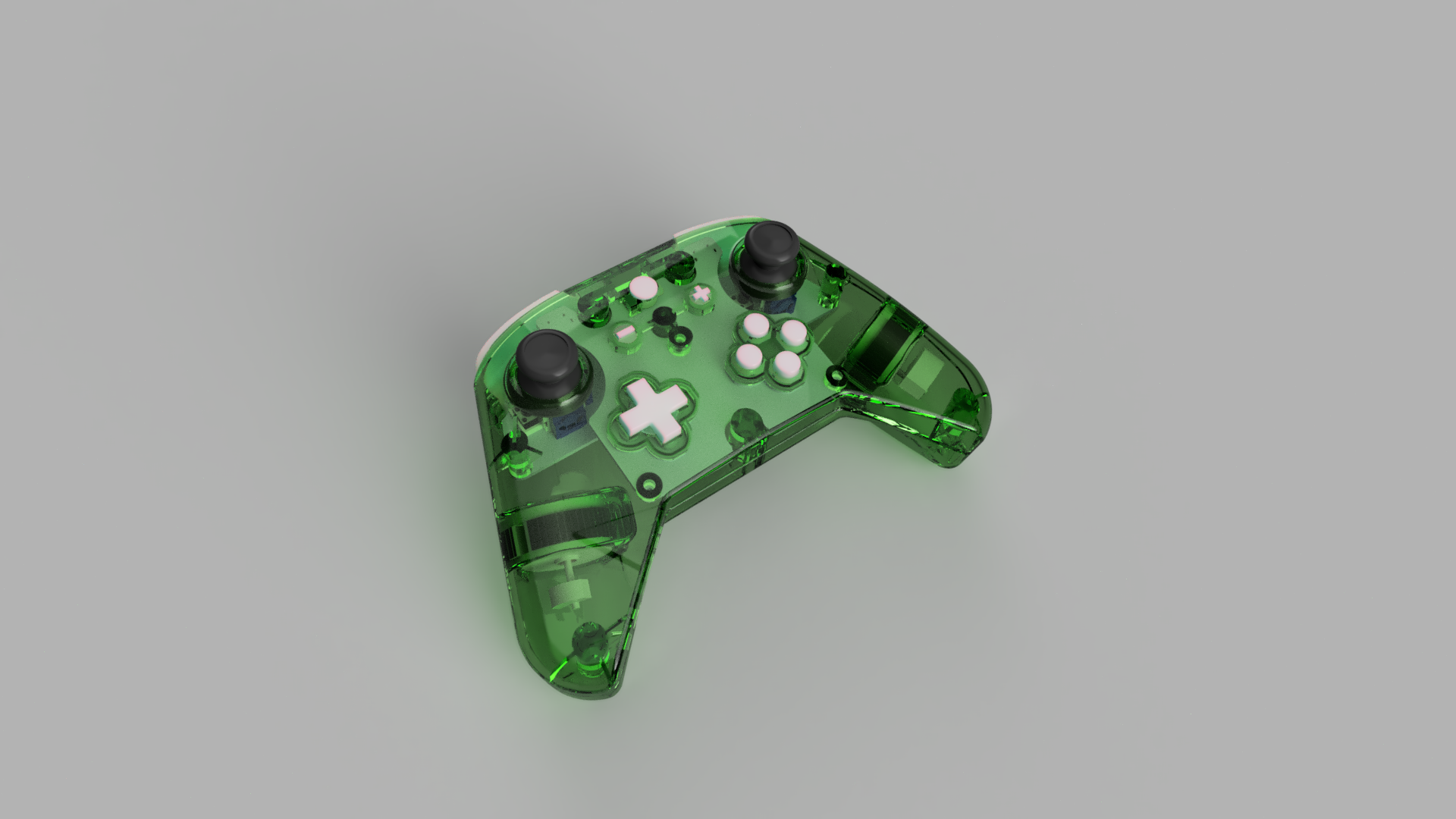
The Wii U gamepad layout is a fan-favourite for many gamers yet it is rarely used in the current generation of controllers. This open source project brings the Wii-U layout back but in a shape more akin to an Xbox controller and provides you with a cool piece of tech that you can be proud to say you built yourself!
Features:
For now, this controller is wired only but I plan to add a wireless version of the design at some point in the future!
If you're printing the housing at home on an FDM printer here's some tips to get the best finish possible!
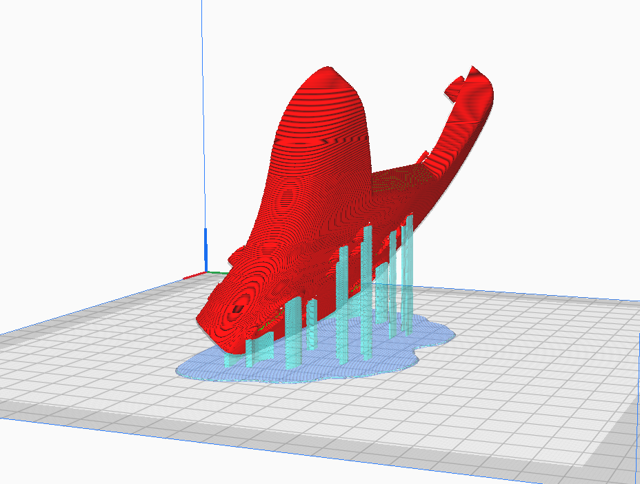
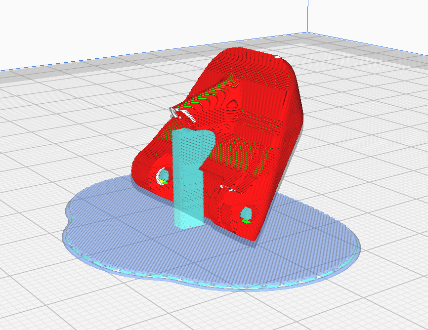
Stand the front housing on its top edge and lean it forward 45 degrees. Enable supports for surfaces over 55 degrees and use a raft to ensure good adhesion to the bed. Ensure Z seam is on the inside! Only minimal supports should be generated, just to support the bottom of the button holes. If you're using a bed-slinger, orient your part so that it runs with the direction your bed moves to reduce wobble.
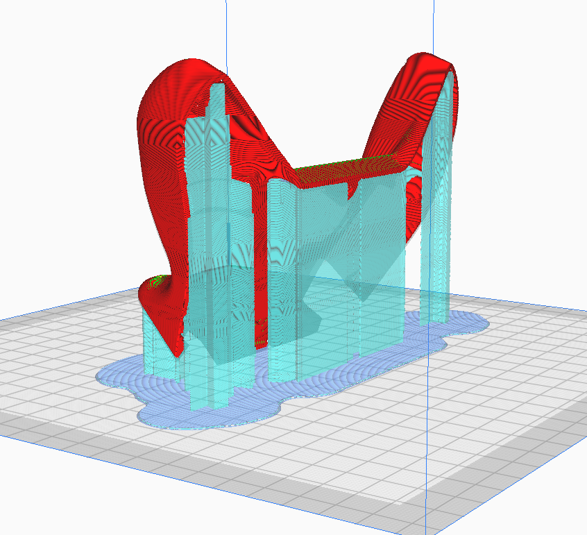
Stand the rear housing on its top edge and lean it back 30 degrees. Enable supports for surfaces over 55 degrees and use a raft to ensure good adhesion to the bed. Ensure Z seam is on the inside! Some supports will be generated on the inside but none are in contact with critical surfaces making cleanup relatively easy. Same as the front, ensure orientation matches your bed movements for bed slinger printers!
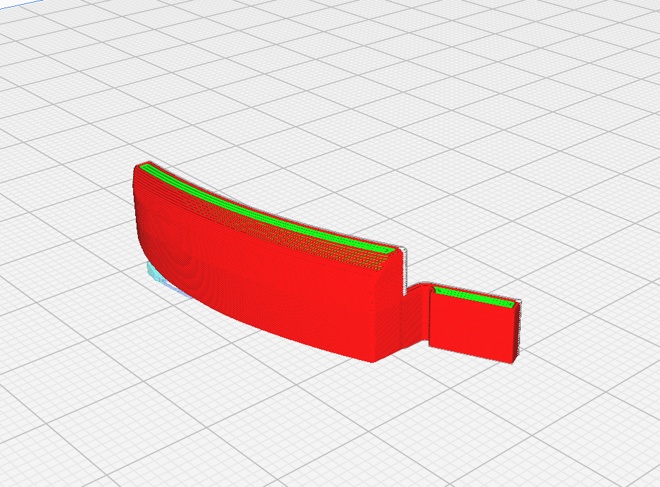
Shoulder buttons should be printed flat on the bed, to ensure the spring is working with the layers rather than against them. Enable supports so the top edge of the buttons aren't left hanging.
Stand trigger buttons on their end and rotate forward 30 degrees. Enable supports for surfaces over 55 degrees and enable raft. Supports should be generated in the holes and for the magnet mount only leaving very little cleanup required.
1x Front PCB (Must use ENIG finish!)
1x Rear PCB
1x Controller Housing Top
1x Controller Housing Bottom
1x LHS Shoulder Button
1x LHS Trigger
1x RHS Shoulder Button
1x RHS Trigger
1x Switch lite button set - https://www.aliexpress.com/item/1005007266706005.html
1x Switch lite membrane set - https://www.aliexpress.com/item/1005004544710872.html
2x PS5 Hall sensor joysticks - https://www.aliexpress.com/item/1005007688806322.html
1x Xbox rumble motor (pair) - https://www.aliexpress.com/item/1005002877455453.html
2x PS4/5 Trigger Springs - https://www.aliexpress.com/item/1005005844578554.html
2x 3x1mm Neodymium Magnets - https://www.aliexpress.com/item/1005006619263188.html
1x 6028 RGB LED - https://www.aliexpress.com/item/1005003719602946.html
1x WS2811 IC - https://www.aliexpress.com/item/32844615804.html
1x USB Data Cable (End will be removed so only need to ensure it has the correct end for your device on one end of the cable)
5x M3x5x5 Threaded Inserts
2x M2x3.2x3 Threaded Inserts
3x M2x3.2x4 Threaded Inserts
5x M3x8 SHCS Screws
6x M2x4 SHCS Screws
Follow the diagram below for locations of components. Pay close attention to orientation of parts U1, Y1, U7 and D1 as they can be fitted in the wrong direction and cause damage. Align marks on all these components with the alignment marks on the PCB.
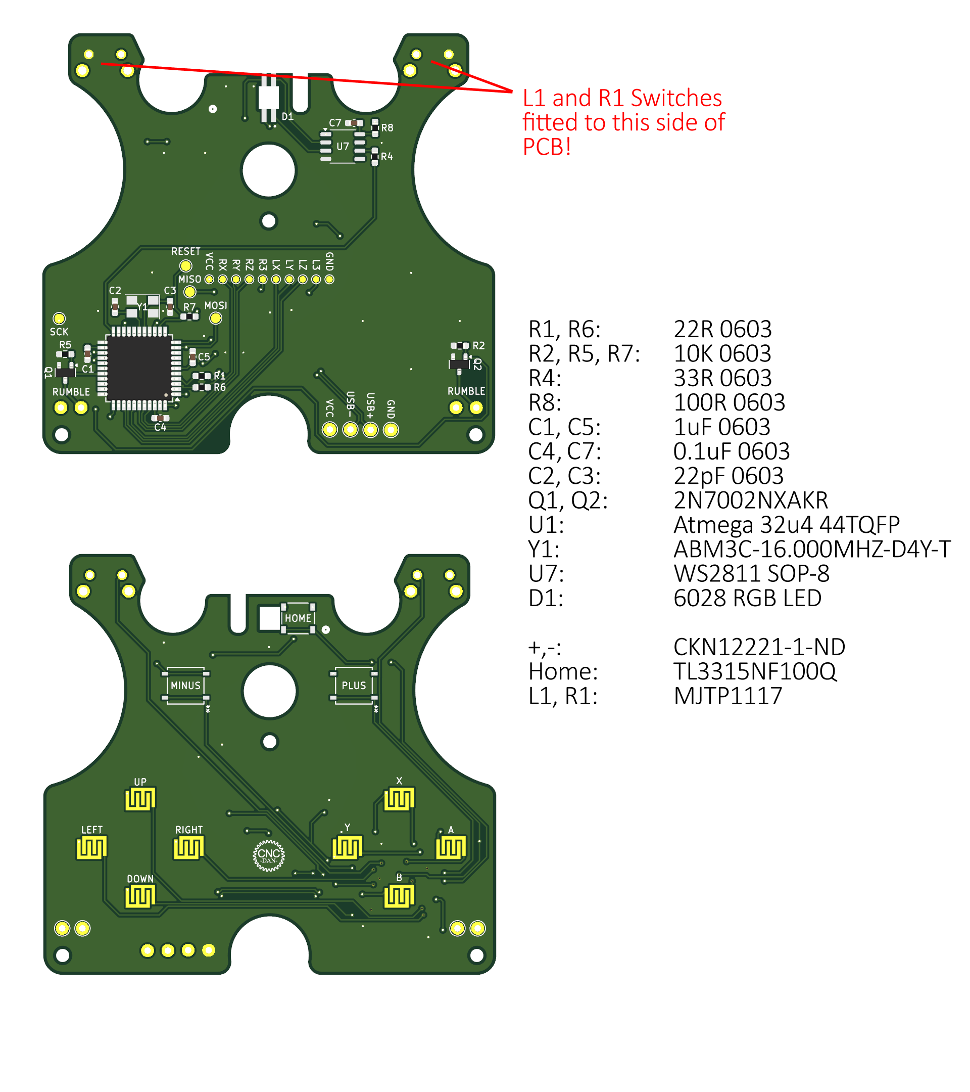
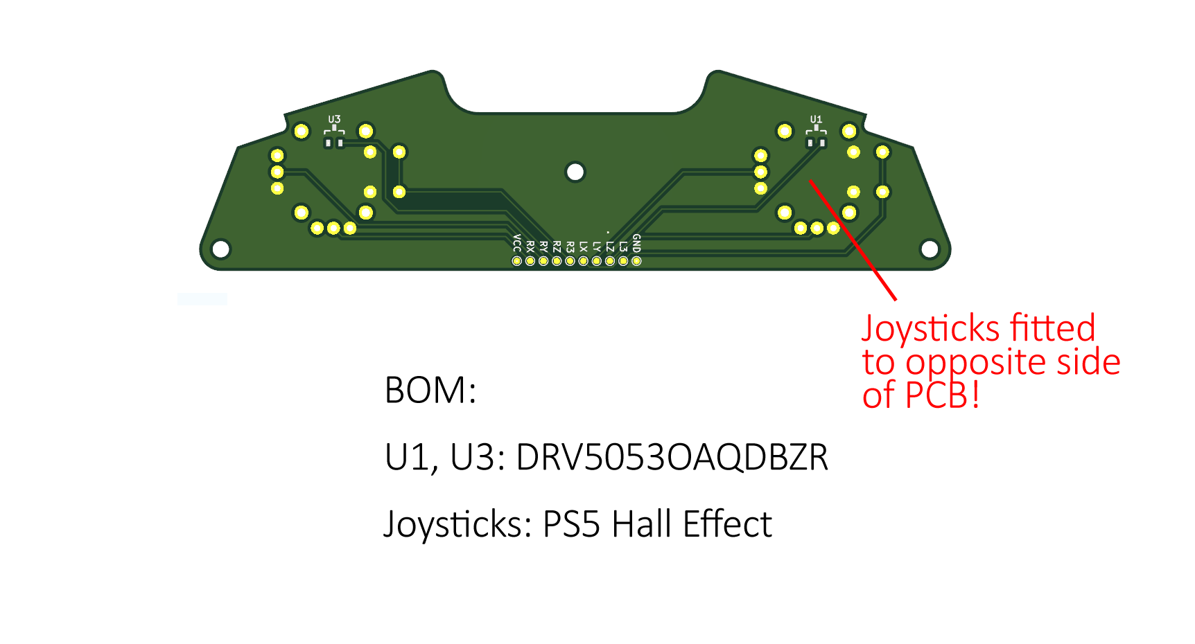
Follow the diagram below for locations of components. Fit joysticks to opposite side of PCB.
You will need to install these libraries to be able to compile the code:
XInput: https://github.com/dmadison/ArduinoXInput
FastLED: https://github.com/FastLED/FastLED
Then simply compile and upload to your controller using the Leonardo w/xinput board option. Please note, once the code is uploaded you will need to re-flash the bootloader to be able to upload code again due to a limitation in the way the xinput library works.
| Qty | Value | Footprint | References |
|---|---|---|---|
| 4 | MOSI | TestPoint:TestPoint_THTPad_D2.0mm_Drill1.0mm | M1_N1, M1_P1, M2_N1, M2_P1 |
| 3 | 10K | Resistor_SMD:R_0603_1608Metric_Pad0.98x0.95mm_HandSolder | R2, R5, R7 |
| 2 | 0.1uF | Capacitor_SMD:C_0603_1608Metric_Pad1.08x0.95mm_HandSolder | C4, C7 |
| 2 | 1uF | Capacitor_SMD:C_0603_1608Metric_Pad1.08x0.95mm_HandSolder | C1, C5 |
| 2 | 22pF | Capacitor_SMD:C_0603_1608Metric_Pad1.08x0.95mm_HandSolder | C2, C3 |
| 2 | 22r | Resistor_SMD:R_0603_1608Metric_Pad0.98x0.95mm_HandSolder | R1, R6 |
| 2 | 2N7002 | Package_TO_SOT_SMD:SOT-23 | Q1, Q2 |
| 2 | ~ | Parts:MJTP1117 | U2, U4 |
| 1 | 100R | Resistor_SMD:R_0603_1608Metric_Pad0.98x0.95mm_HandSolder | R8 |
| 1 | A | Parts:Membrane Button Small | SW1 |
| 1 | ATmega32U4-A | Package_QFP:TQFP-44_10x10mm_P0.8mm | U1 |
| 1 | B | Parts:Membrane Button Small | SW2 |
| 1 | Crystal_GND24 | Crystal:Crystal_SMD_5032-4Pin_5.0x3.2mm | Y1 |
| 1 | DOWN | Parts:Membrane Button Small | SW6 |
| 1 | GND | TestPoint:TestPoint_THTPad_D2.0mm_Drill1.0mm | GND2 |
| 1 | GND | TestPoint:TestPoint_Pad_D1.0mm | GND1 |
| 1 | HOME | Parts:TL3315NF100Q_EWI | SW9 |
| 1 | L3 | TestPoint:TestPoint_Pad_D1.0mm | L3 |
| 1 | LED_BRGK | Parts:LED_T36K3BGR-05D000121U1930 | D1 |
| 1 | LEFT | Parts:Membrane Button Small | SW7 |
| 1 | LX | TestPoint:TestPoint_Pad_D1.0mm | LX1 |
| 1 | LY | TestPoint:TestPoint_Pad_D1.0mm | LY1 |
| 1 | LZ | TestPoint:TestPoint_Pad_D1.0mm | LZ1 |
| 1 | MINUS | Parts:SMT_FS | U5 |
| 1 | MISO | TestPoint:TestPoint_Pad_D1.5mm | MI_1 |
| 1 | MOSI | TestPoint:TestPoint_Pad_D1.5mm | MO_1 |
| 1 | PLUS | Parts:SMT_FS | U6 |
| 1 | R3 | TestPoint:TestPoint_Pad_D1.0mm | R3 |
| 1 | R33 | Resistor_SMD:R_0603_1608Metric_Pad0.98x0.95mm_HandSolder | R4 |
| 1 | RESET | TestPoint:TestPoint_Pad_D1.5mm | R_1 |
| 1 | RIGHT | Parts:Membrane Button Small | SW8 |
| 1 | RX | TestPoint:TestPoint_Pad_D1.0mm | RX1 |
| 1 | RY | TestPoint:TestPoint_Pad_D1.0mm | RY1 |
| 1 | RZ | TestPoint:TestPoint_Pad_D1.0mm | RZ1 |
| 1 | SCK | TestPoint:TestPoint_Pad_D1.5mm | S_1 |
| 1 | UP | Parts:Membrane Button Small | SW5 |
| 1 | USB+ | TestPoint:TestPoint_THTPad_D2.0mm_Drill1.0mm | USB+1 |
| 1 | USB- | TestPoint:TestPoint_THTPad_D2.0mm_Drill1.0mm | USB-1 |
| 1 | VCC | TestPoint:TestPoint_Pad_D1.0mm | VCC1 |
| 1 | VCC | TestPoint:TestPoint_THTPad_D2.0mm_Drill1.0mm | VCC2 |
| 1 | WS2811 | Package_SO:SOP-8_3.9x4.9mm_P1.27mm | U7 |
| 1 | X | Parts:Membrane Button Small | SW3 |
| 1 | Y | Parts:Membrane Button Small | SW4 |
dmcke5/XWii-Controller
The Wii U gamepad layout is a fan-favourite for many gamers yet it is rarely used in the current generation of controllers.

dmcke5/NucDeck
The Open Source DIY Handheld Gaming PC!


carlos-paniagua/TapeTicsProject
This repository contains the hardware and software design files for TapeTics

JCohner/booth
Using 1000 NeoPixels with FastLED library we are controlling a custom built DJ booths lighting. The NeoPixels are organzied into rectangles on a DJ of which the light difuses around the rectnagle.

TheBlueManCoding/ModularControlPanel
Mechanics, PCB and Software for my modular control panel that is used with my cnc machine driven by LinuxCnc

CarlRaymond/RotaryEncoderBreakout
Breakout board for EC12PLRGB rotary encoder with RGB LED.
It measures 70 × 65 mm and has 2 copper layers, 1.6 mm thick.
54 parts, built around the ATMEGA32U4-AU and WS2811. The full list of its parts is on this page, with links to each part's symbol and footprint where PCBKit's library has them.
From the dmcke5/XWii-Controller repository on GitHub, at the commit this page was made from: the board is PCB's/KiCad Project Files/Front PCB/Game Controller - Front PCB.kicad_pcb and its schematic PCB's/KiCad Project Files/Front PCB/Game Controller - Front PCB.kicad_sch. PCBKit opens the board in the browser, with nothing to install.
Its repository publishes it under the CERN-OHL-S-2.0 licence: you may reuse it on that licence's terms (keep the author's notice, and for a copyleft licence share your changes alike).