2 layers52 × 32 mm
Sar pager
KingCountySAR/iot-beepers
Bringing back our favorite pager alarms for those late night callouts
17 parts

 draarivpatel-ui/blare-clock
BlareClock: XIAO ESP32-C3 desk alarm clock with 2.25in ST7789 TFT, DS3231 RTC, 85dB piezo buzzer, KiCad 8 PCB, and OpenSCAD enclosure
Blare clock is an open-source printed circuit board by draarivpatel-ui, from the draarivpatel-ui/blare-clock repository on GitHub, published under the MIT licence. It is a 2-layer board of 92 × 54 mm with 12 parts on 14 nets, routed with 11 tracks and 0 vias.
It is built around the XIAO ESP32C3 and M2.5. Its parts include 4 switches, 2 ICs and 1 connector. It belongs with the lEDs and displays boards and the ESP32 and RISC-V boards of this library.
Try the Live Interactive Clock & Hardware Inspector: https://aariv.me/blare-clock/
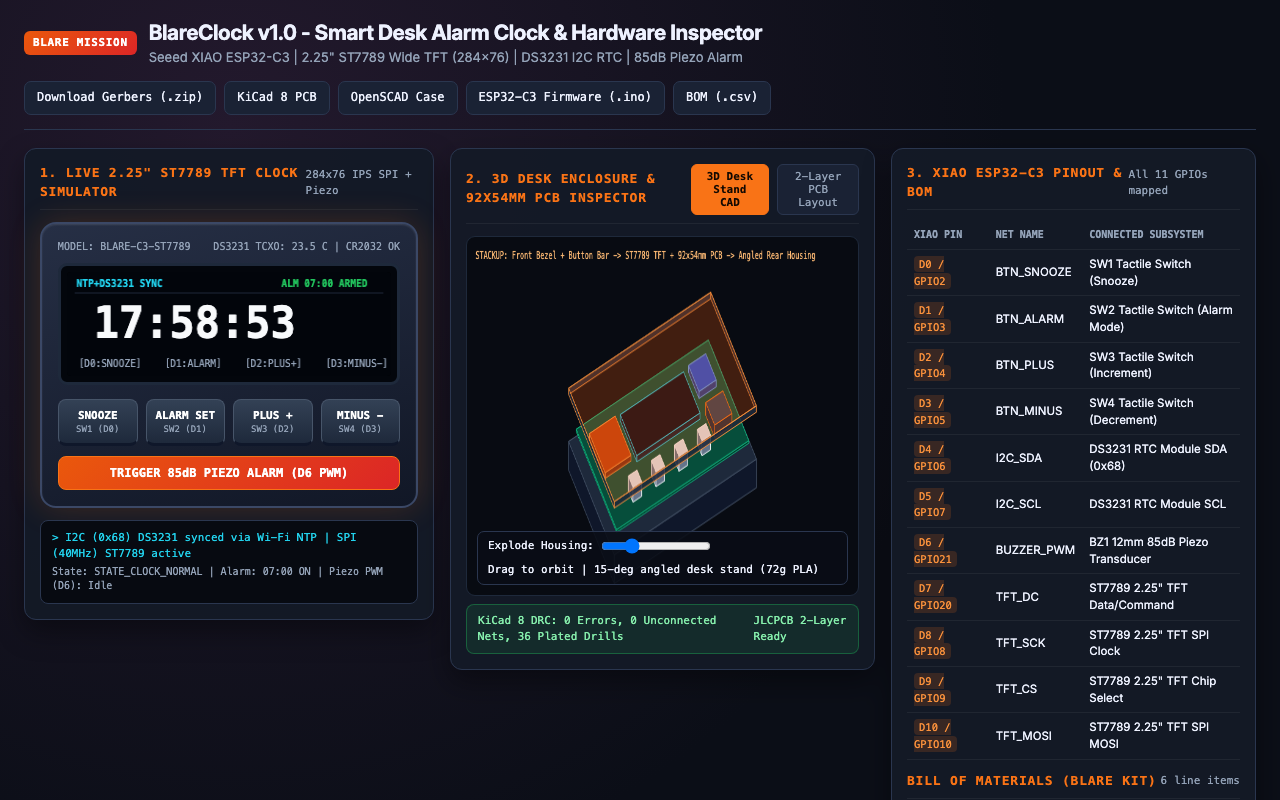
I designed and built BlareClock for the Hack Club Stardance BLARE alarm clock mission. It is a dedicated hardware desk alarm clock powered by a Seeed Studio XIAO ESP32-C3, a wide-aspect 2.25" ST7789 SPI TFT bar display (284x76 IPS), a DS3231 temperature-compensated I2C real-time clock (TCXO) with CR2032 coin-cell backup, a 12mm 85dB passive piezo buzzer, and four front-facing Omron tactile push buttons.
In addition to the complete KiCad 8 schematic, 2-layer carrier PCB (92.0mm x 54.0mm), JLCPCB Gerber archive, 15-degree angled OpenSCAD desk enclosure STLs, and ESP32-C3 Arduino firmware, I also built an interactive browser simulator at https://aariv.me/blare-clock/ where you can test the live 284x76 IPS clock UI, set alarms, trigger the 85dB piezo wake-up melody via Web Audio, inspect the 2-layer PCB traces, and orbit the 3D exploded CAD housing.
For years I used my phone as my morning alarm clock, which meant keeping notifications and a glowing screen within arm's reach of my bed every night. On the flip side, cheap digital bedside clocks drift by several minutes a month and lose their time entirely whenever a wall outlet flickers.
I wanted to build a dedicated, zero-distraction hardware desk clock that solves both problems:
BlareClock boots, the XIAO ESP32-C3 connects briefly to Wi-Fi, pulls UTC time from pool.ntp.org, and writes that exact timestamp into a battery-backed DS3231 TCXO real-time clock. Even if Wi-Fi is down or the USB-C cable is unplugged, the CR2032-backed DS3231 keeps time within ±2 ppm (~1 minute per year) and exposes an onboard die temperature sensor (±0.25°C resolution) for the status bar.284x76 IPS): Instead of a cramped 128x64 OLED or blinding 7-segment LEDs, I chose a wide 2.25" ST7789 bar TFT so the HH:MM:SS readout, armed alarm time, snooze badge, and room temperature fit side by side in crisp typography.SNOOZE, ALARM SET, PLUS +, MINUS -) and a 4-note escalating passive piezo cascade (C6 -> E6 -> G6 -> C7) make sure I can operate it by feel at 6:30 AM.firmware/blare_clock.ino)I structured the ESP32-C3 firmware around a deterministic 5-state controller:
STATE_CLOCK_NORMAL: Renders the live HH:MM:SS readout at 10Hz, polls the DS3231 temperature register every 30 seconds, and checks for exact hour == alarmHour && minute == alarmMin && second == 0 matches when armed. Pressing SNOOZE in normal mode toggles alarmArmed.STATE_EDIT_ALARM_HOUR & STATE_EDIT_ALARM_MIN: Pressing ALARM SET highlights the alarm hour field in amber so PLUS + and MINUS - increment/decrement with wrap-around (0..23); pressing ALARM SET again shifts to minutes (0..59), and a third press commits the new alarm to Preferences NVRAM and arms the clock.STATE_ALARM_RINGING: Flashes the wide TFT border in high-contrast crimson and drives the passive piezo buzzer (GPIO21 LEDC PWM) with an escalating 4-tone square-wave arpeggio (1046Hz, 1318Hz, 1568Hz, 2093Hz). Pressing SNOOZE enters a 9-minute snooze countdown; pressing ALARM SET dismisses the alarm for the day.STATE_SNOOZING: Displays a live SNOOZE 08:59 countdown badge on the ST7789 screen and automatically re-triggers STATE_ALARM_RINGING when the 540-second timer expires.pcb/blare_clock.kicad_pcb): Places the 2.25" ST7789 display module top-center (Y = 6..34mm) directly above the four 6mm Omron tactile buttons (SW1..SW4 at Y = 45mm, spaced 18mm apart) so the entire front face acts as the user interface while the XIAO ESP32-C3, DS3231 RTC module, and 12mm piezo transducer mount cleanly on the rear/inner carrier zone.cad/blare_enclosure.scad): Designed with a 15-degree backward tilt so the display faces your eyes naturally on a desk or nightstand. Includes acoustic louver slots on the rear housing over BZ1, a recessed front bezel for the 2.25" glass panel, and a captive 4-button actuator bar (~72g total PLA).GPIO8, GPIO9, and GPIO2 have boot-strapping behaviors if pulled to the wrong logic level during power-on reset. I wired GPIO8 (D8) as TFT_SCK and GPIO9 (D9) as TFT_CS with external/internal pull-ups so the chip always boots cleanly into normal SPI flash execution mode, even if you hold down SNOOZE (D0 / GPIO2 with internal pull-up) while plugging in USB-C.284x76 SPI framebuffer on every loop iteration caused visible tearing on the seconds counter. In firmware/blare_clock.ino, I tracked lastRenderedSecond and lastUiState so SPI region updates only fire when a digit or state actually changes, keeping the display rock-solid while leaving plenty of CPU headroom for the non-blocking piezo sequencer.| Seeed XIAO ESP32-C3 Pin | Net Name | Connected Hardware |
|---|---|---|
D0 / GPIO2 | BTN_SNOOZE | SW1 Tactile Button (Snooze +9m / Toggle Arm) |
D1 / GPIO3 | BTN_ALARM | SW2 Tactile Button (Cycle Set Hour / Set Minute) |
D2 / GPIO4 | BTN_PLUS | SW3 Tactile Button (Increment Hour / Minute) |
D3 / GPIO5 | BTN_MINUS | SW4 Tactile Button (Decrement Hour / Minute) |
D4 / GPIO6 (SDA) | I2C_SDA | U2 DS3231 RTC Module I2C Data (0x68) |
D5 / GPIO7 (SCL) | I2C_SCL | U2 DS3231 RTC Module I2C Clock |
D6 / GPIO21 | BUZZER_PWM | BZ1 12mm 85dB Passive Piezo Transducer |
D7 / GPIO20 | TFT_DC | J1 2.25" ST7789 SPI TFT Data/Command |
D8 / GPIO8 (SCK) | TFT_SCK | J1 2.25" ST7789 SPI TFT Serial Clock |
D9 / GPIO9 | TFT_CS | J1 2.25" ST7789 SPI TFT Chip Select |
D10 / GPIO10 (MOSI) | TFT_MOSI | J1 2.25" ST7789 SPI TFT Serial Data In |
3V3 / 5V / GND | Power | Common 3V3 logic/backlight rail and stitched GND pour |
| Ref | Qty | Component | Footprint / Package |
|---|---|---|---|
U1 | 1 | Seeed Studio XIAO ESP32-C3 | 14-Pin THT/SMD Module |
J1 | 1 | 2.25" ST7789 Wide SPI TFT LCD (284x76 IPS) | 8-Pin 2.54mm Header |
U2 | 1 | DS3231 Precision I2C RTC Module + CR2032 | 4-Pin 2.54mm Header |
BZ1 | 1 | 12mm 85dB Passive Piezo Buzzer (PS1240P02BT) | MagneticBuzzer_12x9.5mm_P6.5mm |
SW1-SW4 | 4 | 6x6x7mm Omron Tactile Push Buttons (B3F-1050) | SW_PUSH_6mm |
H1-H4 | 4 | M2.5x8mm Screws + M2.5 Brass Heat-Set Inserts | 2.5mm Mounting Holes |
index.html locally) to use the live 2.25" ST7789 clock, press ALARM SET, PLUS +, MINUS -, SNOOZE, or TRIGGER 85dB PIEZO ALARM, inspect the 2-layer PCB copper and silkscreen layers, and orbit the 3D CAD enclosure.pcb/blare_clock.kicad_pro in KiCad 8 to inspect pcb/blare_clock.kicad_sch and pcb/blare_clock.kicad_pcb. JLCPCB-ready Gerbers are archived at pcb/gerbers/blare-clock-gerbers.zip.cad/blare_enclosure.scad in OpenSCAD or slice cad/front_bezel.stl, cad/rear_housing.stl, and cad/button_bar.stl.firmware/blare_clock.ino in Arduino IDE / PlatformIO with RTClib and Adafruit_ST7789 installed.MIT.
| Qty | Value | Footprint | References |
|---|---|---|---|
| 4 | M2.5 | MountingHole:MountingHole_2.5mm_Pad | H1, H2, H3, H4 |
| 1 | ALARM | Button_Switch_THT:SW_PUSH_6mm | SW2 |
| 1 | DS3231_RTC | Timer_RTC:DS3231_Module_4Pin | U2 |
| 1 | MINUS | Button_Switch_THT:SW_PUSH_6mm | SW4 |
| 1 | PIEZO_85dB | Buzzer_Beeper:MagneticBuzzer_12x9.5mm_P6.5mm | BZ1 |
| 1 | PLUS | Button_Switch_THT:SW_PUSH_6mm | SW3 |
| 1 | SNOOZE | Button_Switch_THT:SW_PUSH_6mm | SW1 |
| 1 | ST7789_2.25_TFT | Display_TFT:ST7789_2.25_284x76 | J1 |
| 1 | XIAO_ESP32C3 | Module:Seeed_XIAO_ESP32C3_THT | U1 |
KingCountySAR/iot-beepers
Bringing back our favorite pager alarms for those late night callouts

0rax/esphome-xiao-base
XIAO base board PCB & configuration for ESPHome based sensors.


aayu0-0/SEEED-RS485-Extension-Board-reverse-engineering-project
SEEED RS485 Extension Board reverse-engineering project

AID-IOT/IOT-Memento-Design
A keepsake PCB built at the AICTE IDEA Lab, Poornima College of Engineering. It is a working board as well as a memento: a Seeed XIAO ESP32C3 drives four WS2812B LEDs and reads a BMP280 pressure/temperature sensor, and…
It measures 92 × 54 mm and has 2 copper layers, 1.6 mm thick.
12 parts, built around the XIAO ESP32C3 and M2.5. The full list of its parts is on this page, with links to each part's symbol and footprint where PCBKit's library has them.
From the draarivpatel-ui/blare-clock repository on GitHub, at the commit this page was made from: the board is pcb/blare_clock.kicad_pcb and its schematic pcb/blare_clock.kicad_sch. PCBKit opens the board in the browser, with nothing to install.
Its repository publishes it under the MIT licence: you may reuse it on that licence's terms (keep the author's notice, and for a copyleft licence share your changes alike).