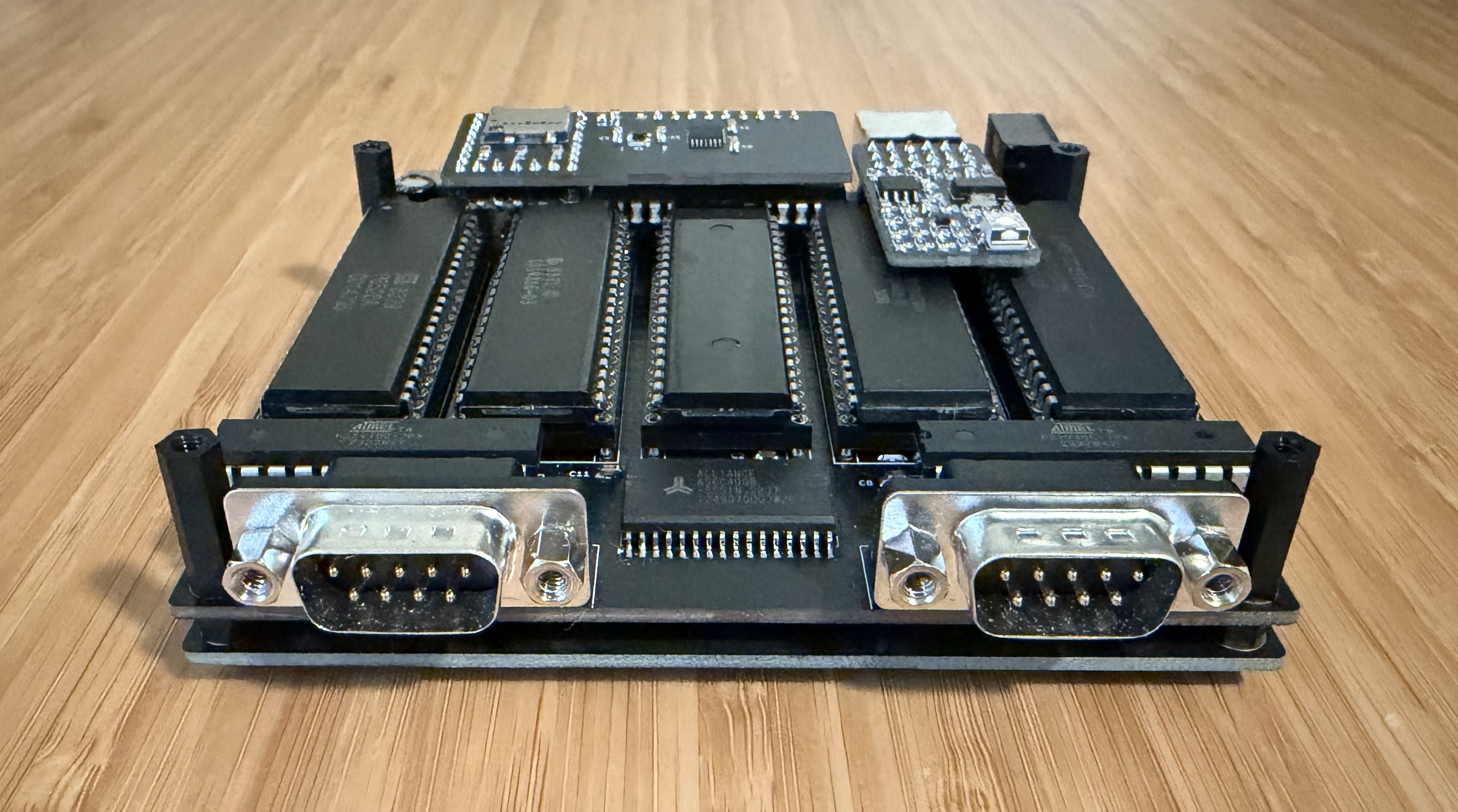
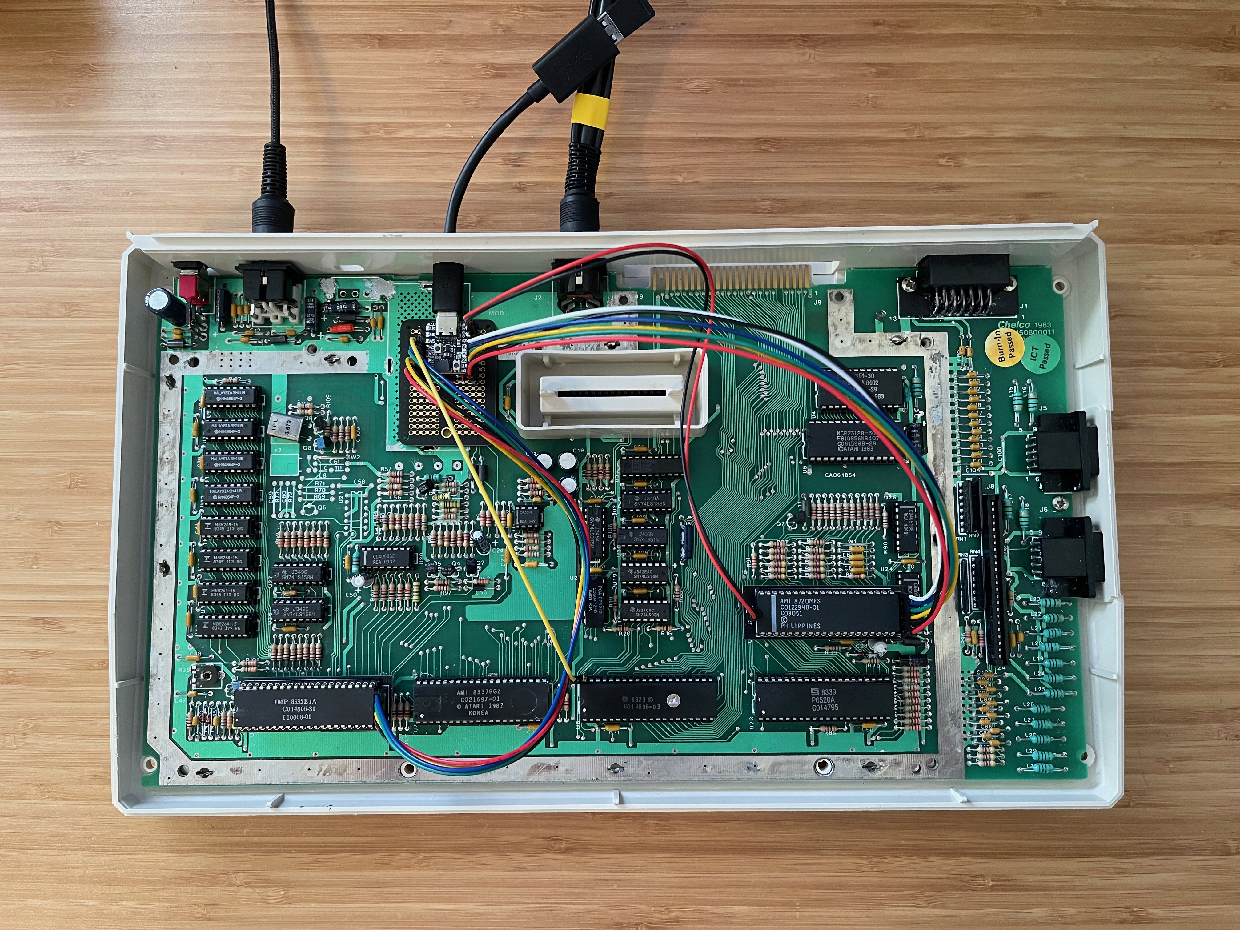
4 layers101.6 × 101.6 mm

 dpicken/atari-hw6
Hardware for Atari 8-bit projects
Sbc sd is an open-source printed circuit board by dpicken, from the dpicken/atari-hw repository on GitHub, published under the MIT licence. It is a 4-layer board of 55.9 × 25.4 mm with 17 parts on 42 nets, routed with 109 tracks and 26 vias.
It is built around the LD39015M33R and TXU0304PW. Its parts include 6 capacitors, 5 connectors, 4 resistors and 2 ICs. It belongs with the retro computing and games and computers and single-board computers boards of this library.


Atari 8-bit hardware projects.
| Qty | Value | Footprint | References |
|---|---|---|---|
| 4 | 10K | Resistor_SMD:R_0805_2012Metric_Pad1.20x1.40mm_HandSolder | R1, R2, R3, R4 |
| 3 | 0.1uF | Capacitor_SMD:C_0805_2012Metric_Pad1.18x1.45mm_HandSolder | C1, C2, C5 |
| 2 | 1uF | Capacitor_SMD:C_0805_2012Metric_Pad1.18x1.45mm_HandSolder | C3, C4 |
| 1 | 104031-0811 | Connector_Card:microSD_HC_Molex_104031-0811 | J5 |
| 1 | 4.7uF | Capacitor_SMD:C_0805_2012Metric_Pad1.18x1.45mm_HandSolder | C6 |
| 1 | LD39015M33R | Package_TO_SOT_SMD:SOT-23-5 | U2 |
| 1 | MC_IO-bottom | Connector_PinHeader_2.54mm:PinHeader_1x05_P2.54mm_Vertical | J4 |
| 1 | MC_IO-lhs | Connector_PinHeader_2.54mm:PinHeader_1x09_P2.54mm_Vertical | J2 |
| 1 | MC_IO_PWR-rhs | Connector_PinHeader_2.54mm:PinHeader_1x09_P2.54mm_Vertical | J3 |
| 1 | SIO-Header | Connector_PinHeader_2.54mm:PinHeader_1x10_P2.54mm_Vertical | J1 |
| 1 | TXU0304 | Package_SO:TSSOP-14_4.4x5mm_P0.65mm | U1 |


anttikes/usb-fm-radio
Repository for an USB-plugged FM radio project, consisting of the firmware, cross-platform user interface and PCB / Schematic portions

elcojacobs/eva-toolboard
Breakout board for EVA to mount to the back of a Nema 17 or name 17 motor. (31mm hole spacing or 43.8mm diagonally).


yannidd/one-button-interface
PCB layout and schematic and Arduino code for a single push-button interface that can be used to turn a device on/off as well as a user input to interact with the firmware on a microcontroller.

themainframe/led-matrix-driver-pcb
PCB CAM files for my LED Matrix Driver Project based on ESP32

L0czek/rakieta
The starter board provides the ignition impulse to fire the engine. It includes an I2C IO expander and an 8-channel digital comparator to require a correct safety byte/address to be present before firing.

It measures 55.9 × 25.4 mm and has 4 copper layers, 4.69 mm thick.
17 parts, built around the LD39015M33R and TXU0304PW. The full list of its parts is on this page, with links to each part's symbol and footprint where PCBKit's library has them.
From the dpicken/atari-hw repository on GitHub, at the commit this page was made from: the board is sbc-sd/sbc-sd.kicad_pcb and its schematic gtia-interposer/gtia-interposer.kicad_sch. PCBKit opens the board in the browser, with nothing to install.
Its repository publishes it under the MIT licence: you may reuse it on that licence's terms (keep the author's notice, and for a copyleft licence share your changes alike).