4 layers180.8 × 300.3 mm
Dilemma
Bastardkb/Dilemma
The Dilemma is a vertical stagger low-profile keyboard with mods.
383 parts590

 dotcypress/upico135
uConsole RP2040 Expansion Card
Upico is an open-source printed circuit board by dotcypress, from the dotcypress/upico repository on GitHub, published under the Apache-2.0 licence. It is a 6-layer board of 36 × 77 mm with 72 parts on 101 nets, routed with 1,120 tracks and 139 vias.
It is built around the RP2040 and USBLC6-2P6. Its parts include 23 capacitors, 23 resistors, 7 ICs, 6 connectors and 1 diode. It belongs with the RP2040 boards of this library.


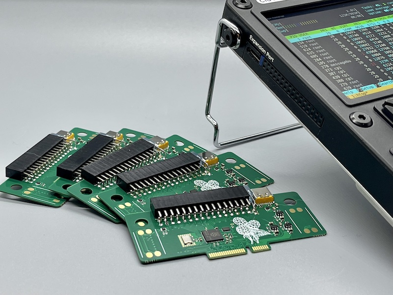
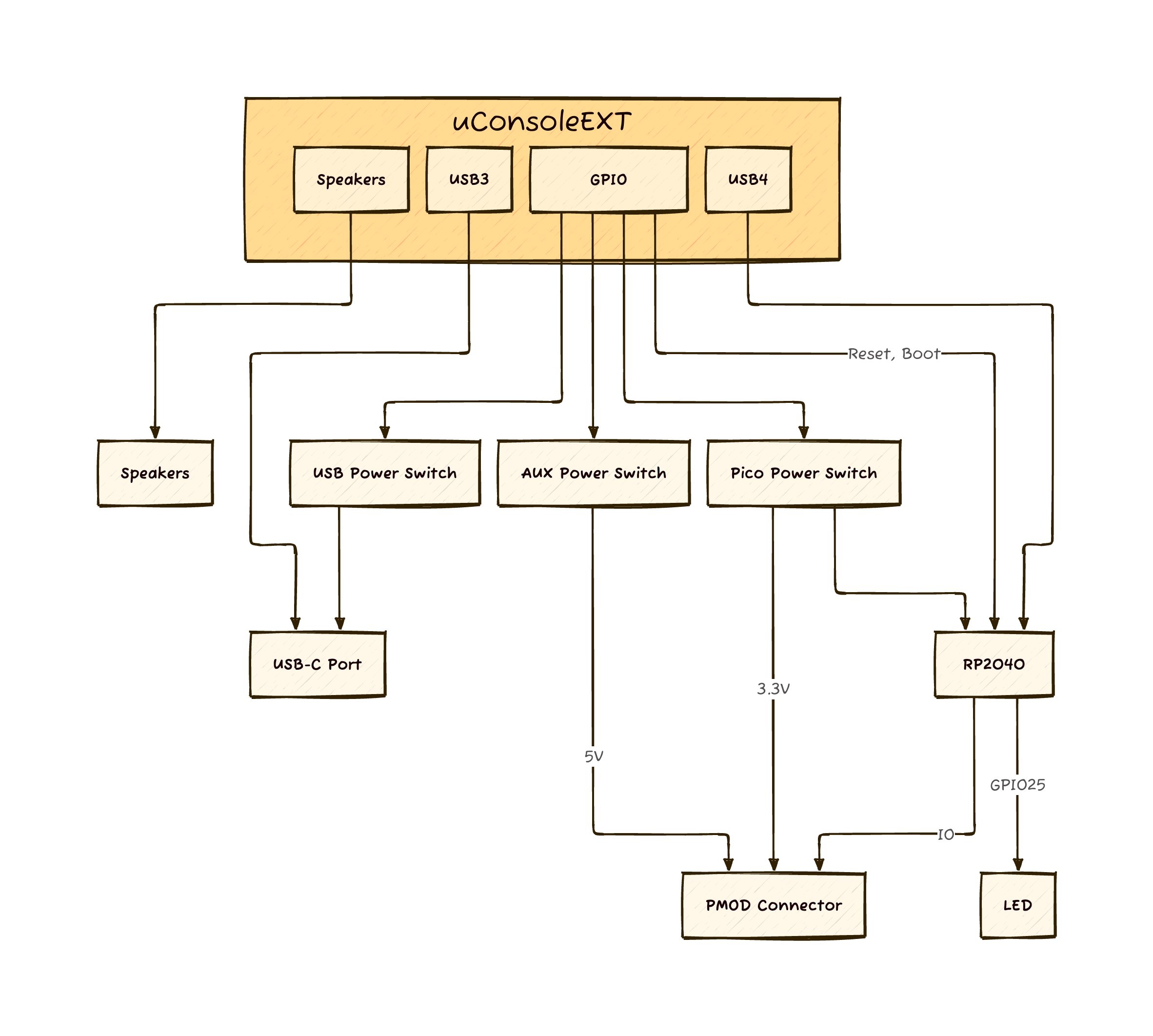
uPico is a RP2040 powered expansion card designed to enhance the capabilities of Clockwork's uConsole.
⚠️ Only R-01 and CM4 core are supported by control application. Work in progress for A04/A06 core modules.
Second project name is atto, cause 10−6 * 10-12 = 10-18 🤓

mkdir dist && tar -xzf upico_%version%.%core%.tar.gz -C distcd dist && sudo ./install.shcd .. && rm -rf distupico helpgit clone git@github.com:dotcypress/upico.git && cd upicocargo build --releasesudo cp target/release/upico /usr/local/bin/sudo cp upico.service /etc/systemd/system/sudo systemctl enable upicosudo systemctl start upicoecho 'SUBSYSTEM=="usb",ATTRS{idVendor}=="1209",ATTRS{idProduct}=="bc07",MODE="0660",GROUP="plugdev"' > /etc/udev/rules.d/50-upico-permissions.rulesudevadm control --reload-rulesupico helpwget https://rptl.io/pico-blinkupico install pico-blink or upico install -m pico-blink if automount is disabled for hot-plug devices.See other examples: https://github.com/raspberrypi/pico-examples
╔══════╦══════╗
║ AUX  ║ AUX  ║
╠══════╬══════╣
║ VDD  ║ VDD  ║
║ GND  ║ GND  ║
║ IO3  ║ IO7  ║
║ IO2  ║ IO6  ║
║ IO1  ║ IO5  ║
║ IO0  ║ IO4  ║
╠══════╬══════╣
║ IO27 ║ IO29 ║
║ IO26 ║ IO28 ║
║ IO18 ║ IO19 ║
╠══════╬══════╣
║ VDD  ║ VDD  ║
║ GND  ║ GND  ║
║ IO11 ║ IO15 ║
║ IO10 ║ IO14 ║
║ IO9  ║ IO13 ║
║ IO8  ║ IO12 ║
╚══════╩══════╝Licensed under either of
at your option.
Unless you explicitly state otherwise, any contribution intentionally submitted for inclusion in the work by you, as defined in the Apache-2.0 license, shall be dual licensed as above, without any additional terms or conditions.
| Qty | Value | Footprint | References |
|---|---|---|---|
| 12 | 100nF | Capacitor_SMD:C_0402_1005Metric | C3, C4, C7, C8, C9, C10, C11, C12, C13, C18, C19, C20 |
| 7 | 10uF | Capacitor_SMD:C_0603_1608Metric | C14, C15, C16, C17, C21, C22, C23 |
| 7 | DNP | Resistor_SMD:R_0402_1005Metric | R2, R6, R7, R8, R9, R12, R13 |
| 4 | 10K | Resistor_SMD:R_0402_1005Metric | R17, R18, R19, R20 |
| 3 | AP22652_3x | Package_TO_SOT_SMD:SOT-23-6 | U5, U6, U7 |
| 2 | 100K | Resistor_SMD:R_0402_1005Metric | R21, R22 |
| 2 | 1K | Resistor_SMD:R_0402_1005Metric | R1, R3 |
| 2 | 2.2K | Resistor_SMD:R_0402_1005Metric | R10, R11 |
| 2 | 27R | Resistor_SMD:R_0402_1005Metric | R4, R5 |
| 2 | 27pF | Capacitor_SMD:C_0402_1005Metric | C1, C2 |
| 2 | 4.7uF | Capacitor_SMD:C_0402_1005Metric | C5, C6 |
| 2 | 56K | Resistor_SMD:R_0402_1005Metric | R15, R16 |
| 2 | MountingHole | MountingHole:MountingHole_5.3mm_M5 | H1, H2 |
| 2 | USBLC6-2P6 | Package_TO_SOT_SMD:SOT-666 | U3, U4 |
| 2 | uConsoleSpeaker | @upico:speaker | J5, J6 |
| 1 | +3.3V | TestPoint:TestPoint_Pad_D1.0mm | TP2 |
| 1 | +5V | TestPoint:TestPoint_Pad_D1.0mm | TP3 |
| 1 | 12MHz | Crystal:Crystal_SMD_5032-2Pin_5.0x3.2mm | Y1 |
| 1 | 47K | Resistor_SMD:R_0402_1005Metric | R23 |
| 1 | 510R | Resistor_SMD:R_0402_1005Metric | R14 |
| 1 | BOOT | TestPoint:TestPoint_Pad_D1.0mm | TP6 |
| 1 | Camera | Connector_FFC-FPC:Hirose_FH12-22S-0.5SH_1x22-1MP_P0.50mm_Horizontal | J4 |
| 1 | GND | TestPoint:TestPoint_Pad_D1.0mm | TP1 |
| 1 | LED | LED_THT:LED_SideEmitter_Rectangular_W4.5mm_H1.6mm | D1 |
| 1 | RP2040 | Package_DFN_QFN:QFN-56-1EP_7x7mm_P0.4mm_EP3.2x3.2mm | U2 |
| 1 | RUN | TestPoint:TestPoint_Pad_D1.0mm | TP5 |
| 1 | USB D+ | TestPoint:TestPoint_Pad_D1.0mm | TP7 |
| 1 | USB D- | TestPoint:TestPoint_Pad_D1.0mm | TP8 |
| 1 | USB_C_Receptacle_USB2.0 | Connector_USB:USB_C_Receptacle_HRO_TYPE-C-31-M-12 | J3 |
| 1 | VDD EN | TestPoint:TestPoint_Pad_D1.0mm | TP4 |
| 1 | W25Q32JVUX | @upico:USON-8_2x3mm_P0.5mm | U1 |
| 1 | uConsoleEXT | @upico:ext | J1 |
| 1 | uPico Connect | Connector_PinSocket_2.54mm:PinSocket_2x16_P2.54mm_Horizontal | J2 |
The 71 most common of 72 parts.
It measures 36 × 77 mm and has 6 copper layers, 0.71 mm thick.
72 parts, built around the RP2040 and USBLC6-2P6. The full list of its parts is on this page, with links to each part's symbol and footprint where PCBKit's library has them.
From the dotcypress/upico repository on GitHub, at the commit this page was made from: the board is pcb/upico.kicad_pcb and its schematic pcb/upico.kicad_sch. PCBKit opens the board in the browser, with nothing to install.
Its repository publishes it under the Apache-2.0 licence: you may reuse it on that licence's terms (keep the author's notice, and for a copyleft licence share your changes alike).
Bastardkb/Dilemma
The Dilemma is a vertical stagger low-profile keyboard with mods.


Twisted-Fields/rp2040-motor-controller
A dual channel brushless motor controller based on the RP2040 microcontroller, designed in Kicad.


