4 layers29.7 × 27.6 mm
 DotBots/DotBot-hardware5
DotBot hardware documents
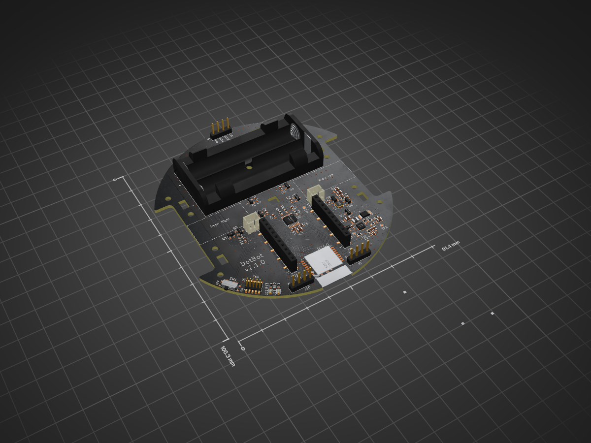
DotBot is an open-source printed circuit board by DotBots, from the DotBots/DotBot-hardware repository on GitHub, published under the BSD-3-Clause licence. It is a 4-layer board of 91.2 × 100.3 mm with 65 parts on 92 nets, routed with 647 tracks and 398 vias.
It is built around the DRV8833PWP, MAX1723EUK and ADP121-AUJZ33R7, with the BT40, LM5158-Q1 and DMP2045U-7 among its other parts. Its parts include 20 capacitors, 14 resistors, 9 ICs, 8 connectors and 4 transistors.


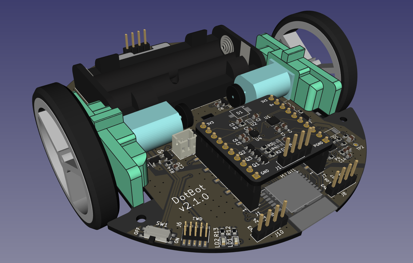
This repository contains hardware projects for the DotBot robot:
This repository also provides a list of off-the-shelf components required to assemble the DotBot:
The Kicad projects are located in the pcb directory.
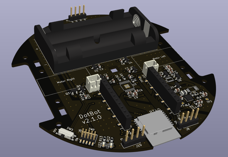
This PCB is based on:
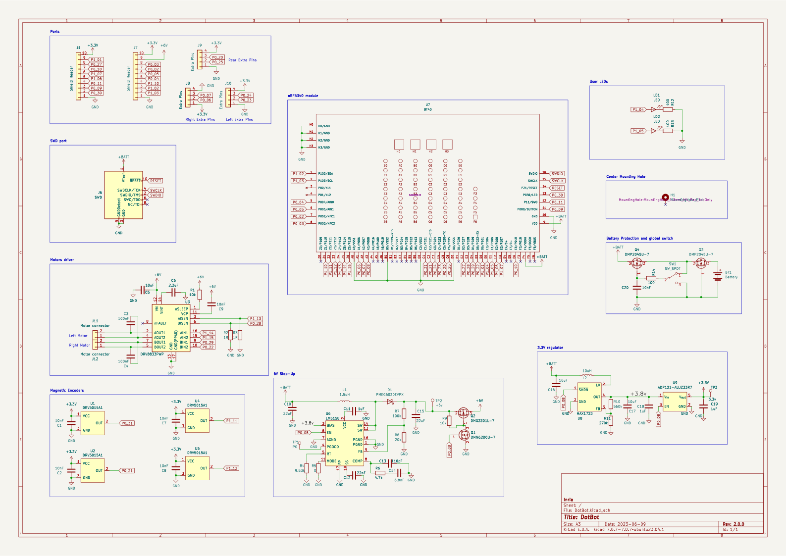
The full resolution schematics can be found at dist/pcb/schematic/DotBot.pdf
This repository already contains the kicad project for one shield in pcb/lh2 which embeds:
To help you start designing new compatible shields, check the shield template kicad project.
The Freecad project, Step files and 3D Manufacturing files are located in the parts directory.
Once you have collected all components and you have prepared them.
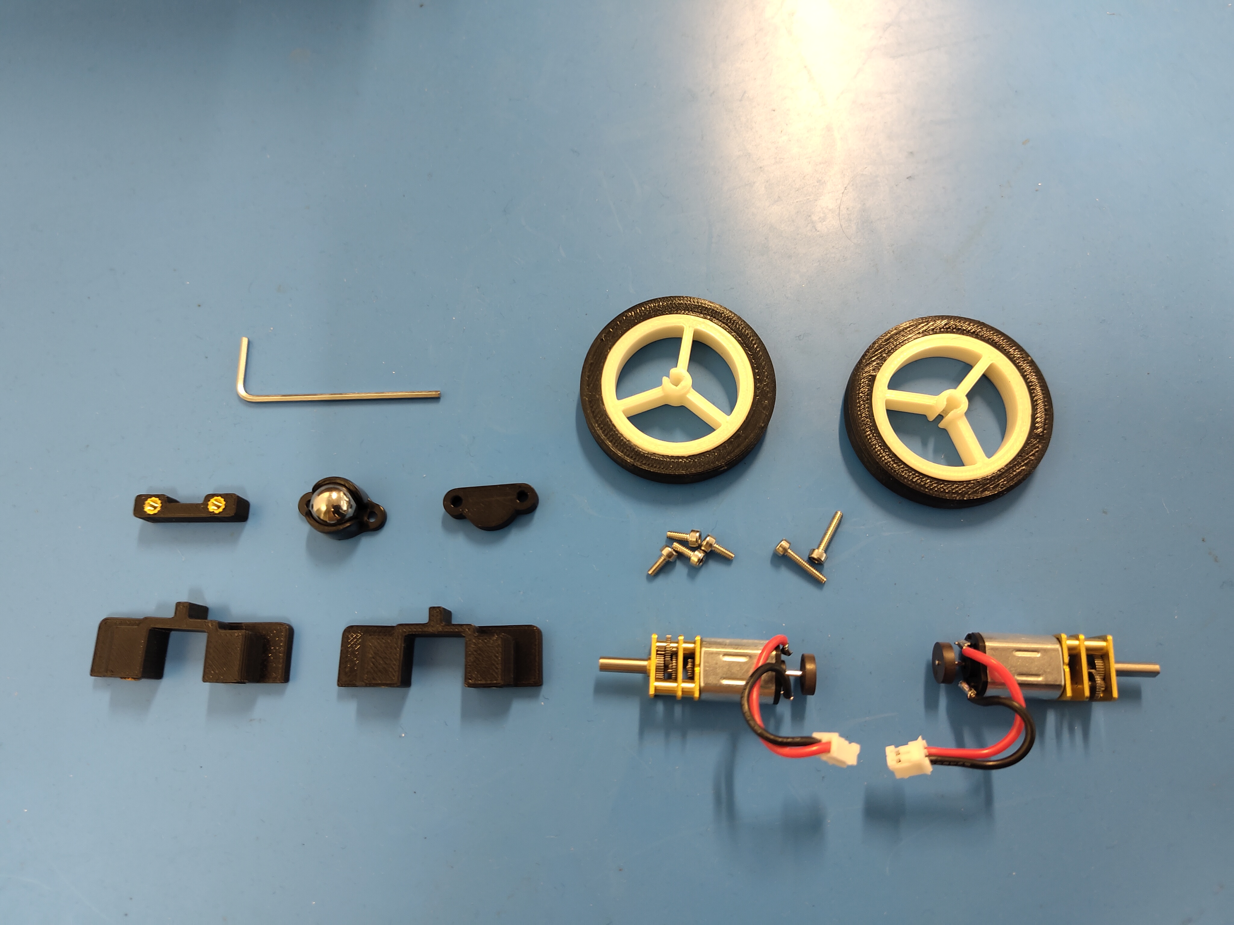
The assembling manual will guide you through the setup of your DotBot.
| Qty | Value | Footprint | References |
|---|---|---|---|
| 6 | 10nF | Capacitor_SMD:C_0603_1608Metric | C1, C2, C7, C8, C9, C20 |
| 4 | DRV5015A1 | Package_TO_SOT_SMD:SOT-23 | U1, U2, U4, U5 |
| 3 | 100 | Resistor_SMD:R_0603_1608Metric | R12, R13, R14 |
| 3 | 10uF | Capacitor_SMD:C_0805_2012Metric | C5, C16, C17 |
| 3 | 1uF | Capacitor_SMD:C_0603_1608Metric | C11, C18, C19 |
| 3 | Extra Pins | Connector_PinHeader_2.54mm:PinHeader_1x04_P2.54mm_Vertical | J8, J9, J10 |
| 2 | 100nF | Capacitor_SMD:C_0603_1608Metric | C3, C4 |
| 2 | 10k | Resistor_SMD:R_0603_1608Metric | R1, R9 |
| 2 | 1R | Resistor_SMD:R_0603_1608Metric | R2, R3 |
| 2 | 22uF | Capacitor_SMD:C_0805_2012Metric | C10, C15 |
| 2 | DMP2045U-7 | Package_TO_SOT_SMD:SOT-23 | Q3, Q4 |
| 2 | LED | LED_SMD:LED_0603_1608Metric | LD1, LD2 |
| 2 | Motor connector | Connector_JST:JST_PH_B2B-PH-K_1x02_P2.00mm_Vertical | J11, J12 |
| 2 | Shield Header | Connector_PinSocket_2.54mm:PinSocket_1x10_P2.54mm_Vertical_SMD_Pin1Left | J1, J7 |
| 1 | +6v | TestPoint:TestPoint_Pad_D1.0mm | TP2 |
| 1 | 0 | Resistor_SMD:R_0603_1608Metric | R5 |
| 1 | 1.5uH | Inductor_SMD:L_1008_2520Metric | L1 |
| 1 | 100k | Resistor_SMD:R_0603_1608Metric | R7 |
| 1 | 10uH | Inductor_SMD:L_Taiyo-Yuden_NR-30xx | L2 |
| 1 | 110pF | Capacitor_SMD:C_0603_1608Metric | C13 |
| 1 | 2.2uF | Capacitor_SMD:C_0603_1608Metric | C6 |
| 1 | 20k | Resistor_SMD:R_0603_1608Metric | R8 |
| 1 | 22nF | Capacitor_SMD:C_0603_1608Metric | C12 |
| 1 | 270k | Resistor_SMD:R_0603_1608Metric | R11 |
| 1 | 3.3v | TestPoint:TestPoint_Pad_D1.0mm | TP3 |
| 1 | 4.7k | Resistor_SMD:R_0603_1608Metric | R6 |
| 1 | 560k | Resistor_SMD:R_0603_1608Metric | R10 |
| 1 | 6.8nF | Capacitor_SMD:C_0603_1608Metric | C14 |
| 1 | 9.53k | Resistor_SMD:R_0603_1608Metric | R4 |
| 1 | ADP121-AUJZ33R7 | Package_TO_SOT_SMD:SOT-23-5 | U9 |
| 1 | BT40 | DotBot:BT40-V3 | U7 |
| 1 | Battery | Battery:BatteryHolder_MPD_BC2AAPC_2xAA | BT1 |
| 1 | DMG2301L-7 | Package_TO_SOT_SMD:SOT-23 | Q2 |
| 1 | DMN62D0U-7 | Package_TO_SOT_SMD:SOT-23 | Q1 |
| 1 | DRV8833PWP | Package_SO:HTSSOP-16-1EP_4.4x5mm_P0.65mm_EP3.4x5mm_Mask2.46x2.31mm_ThermalVias | U3 |
| 1 | LM5158 | Package_DFN_QFN:WQFN-16-1EP_3x3mm_P0.5mm_EP1.6x1.6mm_ThermalVias | U6 |
| 1 | MAX1723 | Package_TO_SOT_SMD:SOT-23-5 | U8 |
| 1 | PG | TestPoint:TestPoint_Pad_D1.0mm | TP1 |
| 1 | PMEG6030EVPX | Diode_SMD:D_SOD-128 | D1 |
| 1 | SWD | Connector_PinHeader_1.27mm:PinHeader_2x05_P1.27mm_Vertical_SMD | J6 |
| 1 | SW_SPDT | DotBot:SW_SPDT_PCM12 | SW1 |
It measures 91.2 × 100.3 mm and has 4 copper layers, 1.6 mm thick.
65 parts, built around the DRV8833PWP, MAX1723EUK, ADP121-AUJZ33R7 and BT40. The full list of its parts is on this page, with links to each part's symbol and footprint where PCBKit's library has them.
From the DotBots/DotBot-hardware repository on GitHub, at the commit this page was made from: the board is pcb/DotBot.kicad_pcb and its schematic pcb/DotBot.kicad_sch. PCBKit opens the board in the browser, with nothing to install.
Its repository publishes it under the BSD-3-Clause licence: you may reuse it on that licence's terms (keep the author's notice, and for a copyleft licence share your changes alike).


Kampi/IoT-Gateway
Open-Source Zigbee, Thread, wM-Bus, LoRa, LoRaWAN gateway for Home Assistant.


joshajohnson/bsidescbr2021
Slides and Design Files for BSides Canberra 2021


