2 layers159.5 × 30 mm
Type f
google/mozc-devices
Circuit diagrams and firmware source code for Gboard DIY keyboards
25 parts3kApache-2.0

 doj/Ultimate-USB-to-Controlport14
Arduino project to convert USB joystick or mouse to digital for use with Commodore or Atari computers
Ultimate USB joystick is an open-source printed circuit board by doj, from the doj/Ultimate-USB-to-Controlport repository on GitHub. It is a 2-layer board of 68.6 × 53.3 mm with 25 parts on 47 nets, routed with 166 tracks and 0 vias.
It belongs with the retro computing and games and keyboards and input boards of this library.
An Arduino project to convert a USB joystick and mouse to digital for use with Commodore or Atari computers.
See the Controllers section below for supported USB devices.
Install the USB Host Shield Library 2.0 version 1.3.2 using the Arduino IDE library manager.
Then compile and upload the program main/main.ino with the Arduino IDE.
Connect a USB joystick, gamepad, mouse, keyboard to the USB Host Shield. If the USB Host Shield (Library) supports the device it will produce events on the Commodore control port. You can also use a USB hub to connect multiple devices.
The following buttons of a gamepad are assigned to the following directions:
| NES | Sony | Control Port |
|---|---|---|
| B | cross | fire |
| A | circle | auto fire A, 10 Hz |
| Y | square | auto fire Y, 5 Hz |
| X | triangle | up |
| n/a | L1 | left |
| n/a | R1 | right |
| L | L2 | left |
| R | R2 | right |
| select | select | fire 2 on POT Y |
| start | start | fire 3 on POT X |
You can configure the frequency of the auto fire from 1 Hz to 255 Hz. To configure the frequency press:
You can switch the directions of all buttons (lefty mode), press: select+start+B+left.
You can switch the Control Port a device uses by pressing: select+start+L2+up
A USB mouse will be used to output the Commodore 1351 mouse protocol on the Pot X and Pot Y control port inputs. The following table shows the mouse button mapping:
| Mouse | Control Port |
|---|---|
| left | fire |
| middle | down |
| right | up |
| wheel up | left |
| wheel down | right |
| left side | left |
| right side | right |
The mouse wheel is using the Micromys protocol. Left and Right side buttons are used on the Microsoft Intellimouse.
The table below shows how keyboard keys are mapped to the control port:
| Key | Control Port |
|---|---|
| up, num 8, w, i | up |
| down, num 2, s, k | down |
| left, 4, a, j | left |
| right, 6, d, l | right |
| ins, space, ~, enter, F1, b | fire (gamepad B) |
| y | auto fire (gamepad Y) |
| x | up (gamepad X) |
| F2 | fire 2 on POT Y (gamepad select) |
| F3 | fire 3 on POT X (gamepad start) |
This project was tested with a Arduino Uno R3 board and the Arduino USB Host Shield. While the USB Host Shield is no longer sold by the Arduino company, you can easily find clones of the board on AliExpress, where you can also buy a clone Arduino Uno board. To connect the resistors and cables (or Sub-D connectors) you can also purchase a Proto Shield R3.
The following picture shows the location of all I/O pins on the Arduino Uno R3 board.

The following table shows how the 2 control ports with [https://en.wikipedia.org/wiki/D-subminiature](D-sub 9) connectors should be connected to the Arduino pins. This suggested connection is for a Commodore 64. You can change the pin assignments in the config.h file. Except for the +5V (which doesn't need to to connected) and the GND, all connections between the Arduino and the control port should be made via a resistor. The exact resistor value is not important, anything in the 100-500 Ohm range should be fine.
Control Port 1
| Arduino | Resistor | D-sub | Function |
|---|---|---|---|
| A0 | 220 Ohm | 1 | Up |
| A1 | 220 Ohm | 2 | Down |
| A2 | 220 Ohm | 3 | Left |
| A3 | 220 Ohm | 4 | Right |
| A5 | 220 Ohm | 5 | Pot Y |
| A4 | 220 Ohm | 6 | Fire |
| (n/c) | - | 7 | +5V |
| GND | - | 8 | GND |
| D2 | 220 Ohm | 9 | Pot X |
Control Port 2
| Arduino | Resistor | D-sub | Function |
|---|---|---|---|
| D4 | 220 Ohm | 1 | Up |
| D5 | 220 Ohm | 2 | Down |
| D6 | 220 Ohm | 3 | Left |
| D7 | 220 Ohm | 4 | Right |
| D1 | 220 Ohm | 5 | Pot Y |
| D8 | 220 Ohm | 6 | Fire |
| (n/c) | - | 7 | +5V |
| GND | - | 8 | GND |
| D3 | 220 Ohm | 9 | Pot X |
Note: On the Arduino pins D0 and D1 are used for the serial debug console. If you connect the control port Pot Y line to D1, you can't use the serial console any more.
If you want to change the Arduino pin assignments, change the config.h file.
If you have a clone USB Host Shield from China it is likely that the 3.3V and 5V power supply to the board and USB device connector are not connected. The solder pads show a gap. Closing them with a soldering iron should make the USB Host Shield operational. See https://esp8266-notes.blogspot.com/2017/08/defective-arduino-usb-host-shield-boards.html for details.
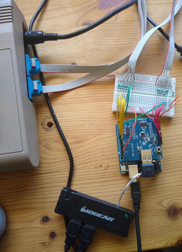
The following picture shows the development prototype with an Arduino Uno, the USB Host Shield, a 4 port USB hub and connections to both Commodore 64 control ports.
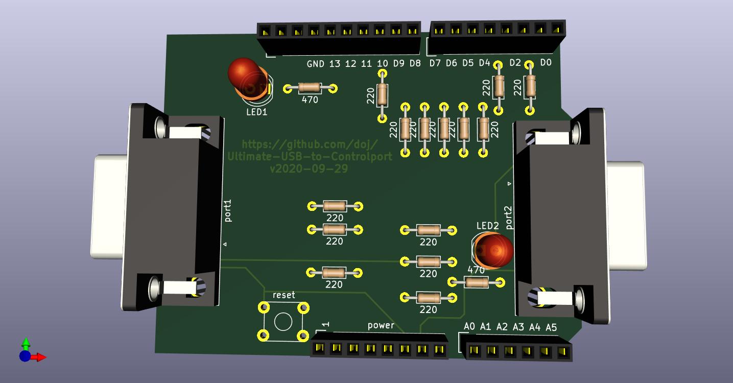
the arduino-shield/ directory contains a KiCad project of an Arduino Uno Shield.
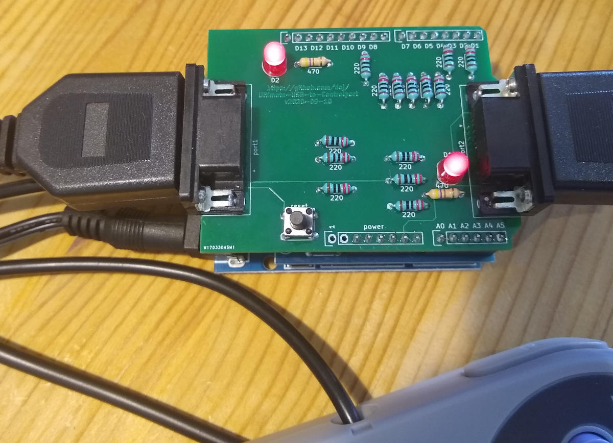
The following picture shows a build of the first version of the shield.
The following changes would improve the Arduino Uni Shield:
The following list shows which features are implemented.
The following controllers have been tested with the software:
Sony Playstation Classic USB controller.

iNNEXT SNES USB controller, which you also find under other brand names like kiwitata, retroflag.

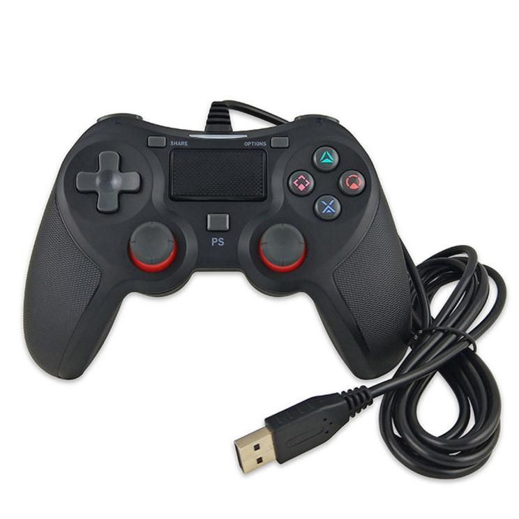
P4-5N USB controller, which costs ~USD20 in 2020 on Amazon.com
Microsoft Intellimouse optical USB.
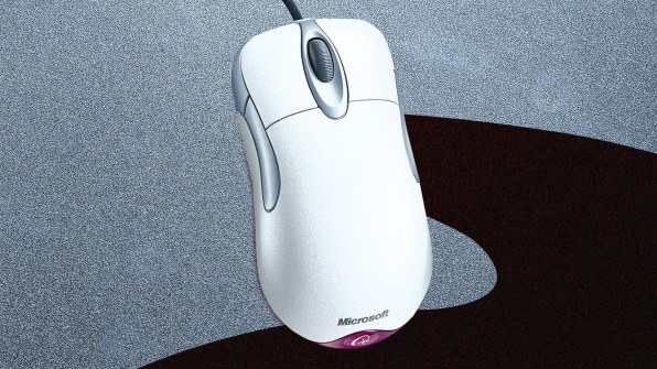
Apple Mighty Mouse wired

generic 3 button + wheel USB mouse
generic USB keyboard
By default the serial debug console is enabled and uses 115200 baud. See the config.h file to configure the baud rate or to disable the debug console output.
the USB Host Shield 2.0 Library does not properly enumerate devices. This software currently works around that issue by using the universal HID device and manually parsing all incoming data packets. This may cause problems for untested USB HID devices.
1351 mouse support on POT is not working yet. When USB data is received the timer1 does not reliably work.
This software uses the arduino-timer library.
Information on Commodore 1351 mouse: http://sensi.org/~svo/[m]ouse/ http://www.zimmers.net/anonftp/pub/cbm/documents/projects/interfaces/mouse/Mouse.html
Information how to read joystick and POT on the C64: https://codebase64.org/doku.php?id=base:io_programming
Information on the USB protocol: http://www.usbmadesimple.co.uk/ums_4.htm
USB Host Shield 2.0 Library with fixes and better debugging messages: https://github.com/doj/USB_Host_Shield_2.0
PSX64 Interface The PSX64 interface connects Playstation controllers to most computers and consoles that use a DB9 joystick port.
PadSwitcher64 is an interface for SNES controllers and Commodore 64 control ports.
Unijoysticle 2 an interface for bluetooth wireless controllers and Commodore 64 control ports.
The following C64 Basic program can be used to test the 2 control ports and the POT of control port 1. You also find it in the GIT repository as joysticktest.prg
10 j = NOT PEEK(56321)
15 b = NOT PEEK(56320)
20 PRINT CHR$(147);
30 IF (j AND 1) THEN PRINT "1U ";
35 IF (b AND 1) THEN PRINT "2U ";
40 IF (j AND 2) THEN PRINT "1D ";
45 IF (b AND 2) THEN PRINT "2D ";
50 IF (j AND 4) THEN PRINT "1L ";
55 IF (b AND 4) THEN PRINT "2L ";
60 IF (j AND 8) THEN PRINT "1R ";
65 IF (b AND 8) THEN PRINT "2R ";
70 IF (j AND 16) THEN PRINT "1F ";
75 IF (b AND 16) THEN PRINT "2F ";
80 PRINT
200 POKE 56322,224 : REM disable keyboard
210 PRINT "POT1X " ; PEEK(54297) ; " POT1Y " ; PEEK(54298)
290 POKE 56322,255 : REM enable keyboard
1000 GOTO 10Write an email to Dirk Jagdmann doj@cubic.org The source code is hosted on https://github.com/doj/Ultimate-USB-to-Controlport
| Date | Changes |
|---|---|
| 2020-05-17 | 1351 fixes |
| 2020-09-29 | add Arduino Uno Shield PCB |
| 2020-09-30 | fix stuck direction when switching control ports |
| Qty | Value | Footprint | References |
|---|---|---|---|
| 14 | 220 | Resistor_THT:R_Axial_DIN0204_L3.6mm_D1.6mm_P7.62mm_Horizontal | 220, 220, 220, 220, 220, 220, 220, 220, 220, 220, 220, 220, 220, 220 |
| 2 | 470 | Resistor_THT:R_Axial_DIN0204_L3.6mm_D1.6mm_P7.62mm_Horizontal | 470, 470 |
| 2 | Commodore_Control_Port | Connector_Dsub:DSUB-9_Female_Horizontal_P2.77x2.84mm_EdgePinOffset4.94mm_Housed_MountingHolesOffset7.48mm | port1, port2 |
| 2 | LED | LED_THT:LED_D5.0mm | LED1, LED2 |
| 1 | Analog | Socket_Arduino_Uno:Socket_Strip_Arduino_1x06 | A0 A1 A2 A3 A4 A5 |
| 1 | Digital | Socket_Arduino_Uno:Socket_Strip_Arduino_1x08 | D7 D6 D5 D4 D2 D0 |
| 1 | Digital | Socket_Arduino_Uno:Socket_Strip_Arduino_1x10 | GND 13 12 11 10 D9 D8 |
| 1 | Power | Socket_Arduino_Uno:Socket_Strip_Arduino_1x08 | power |
| 1 | SW_Push | Button_Switch_THT:SW_TH_Tactile_Omron_B3F-10xx | reset |
google/mozc-devices
Circuit diagrams and firmware source code for Gboard DIY keyboards

davidphilipbarr/Sweep
Sweep - a small promicro based keyboard inspired by the Ferris.


hackclub/OnBoard
💡 Join 1,000 teenagers and make your first PCB with a $100 grant!

xyphro/UsbGpib
Versatile, cheap and portable USB to GPIB converter (USBTMC class based)


jes/scamp-cpu
A homebrew 16-bit CPU with a homebrew Unix-like-ish operating system.

It measures 68.6 × 53.3 mm and has 2 copper layers, 1.6 mm thick.
25 parts. The full list of its parts is on this page, with links to each part's symbol and footprint where PCBKit's library has them.
From the doj/Ultimate-USB-to-Controlport repository on GitHub, at the commit this page was made from: the board is arduino-shield/Ultimate-USB-joystick.kicad_pcb. PCBKit opens the board in the browser, with nothing to install.
Its repository states no licence, so its author keeps all rights: ask doj before reusing the design.