
2 layers130.3 × 105.3 mm

 dohn-joh/liaison16
liaison keyboard
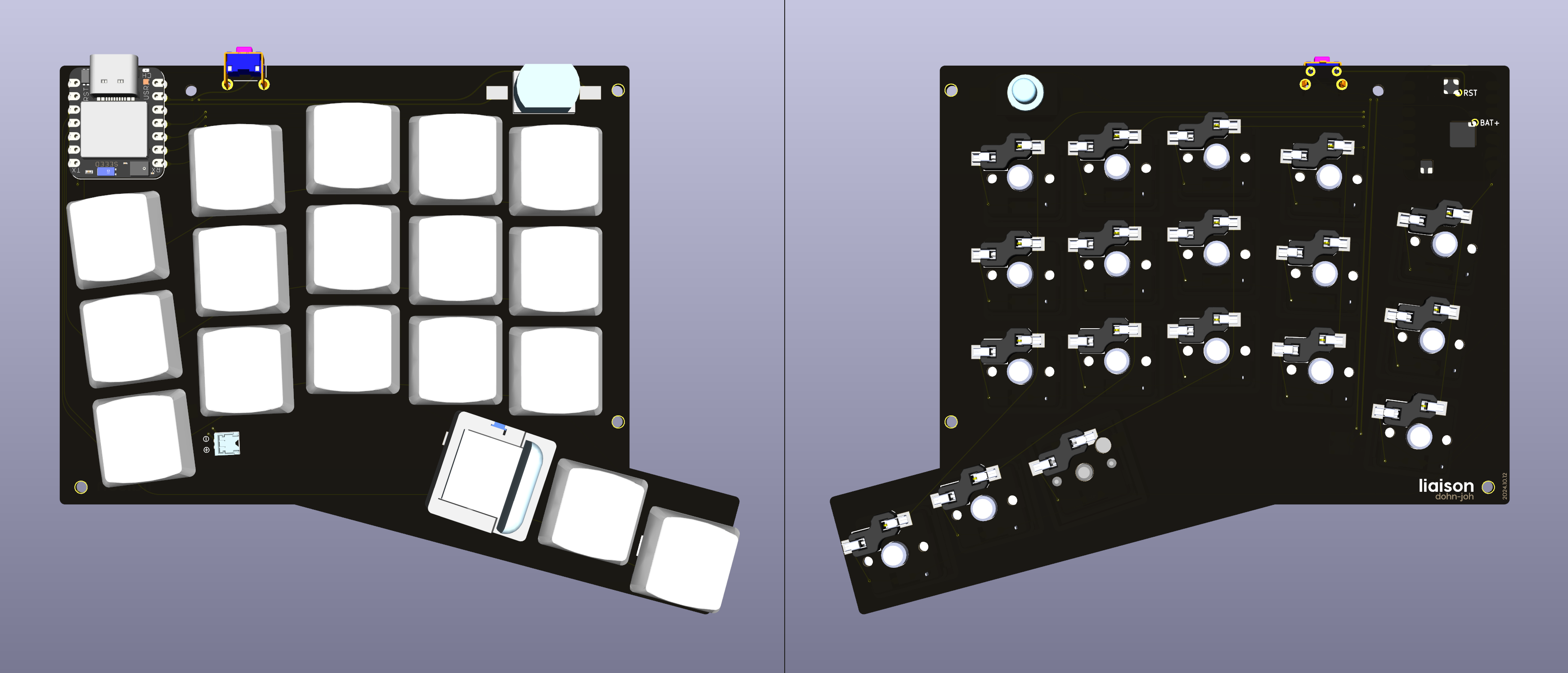
Left render is an open-source printed circuit board by dohn-joh, from the dohn-joh/liaison repository on GitHub, published under the CERN-OHL-P-2.0 licence. It is a 2-layer board of 130 × 105 mm with 44 parts on 35 nets, routed with 157 tracks and 27 vias.
It is built around the SKHLLCA010. Its parts include 20 switches and 18 diodes.
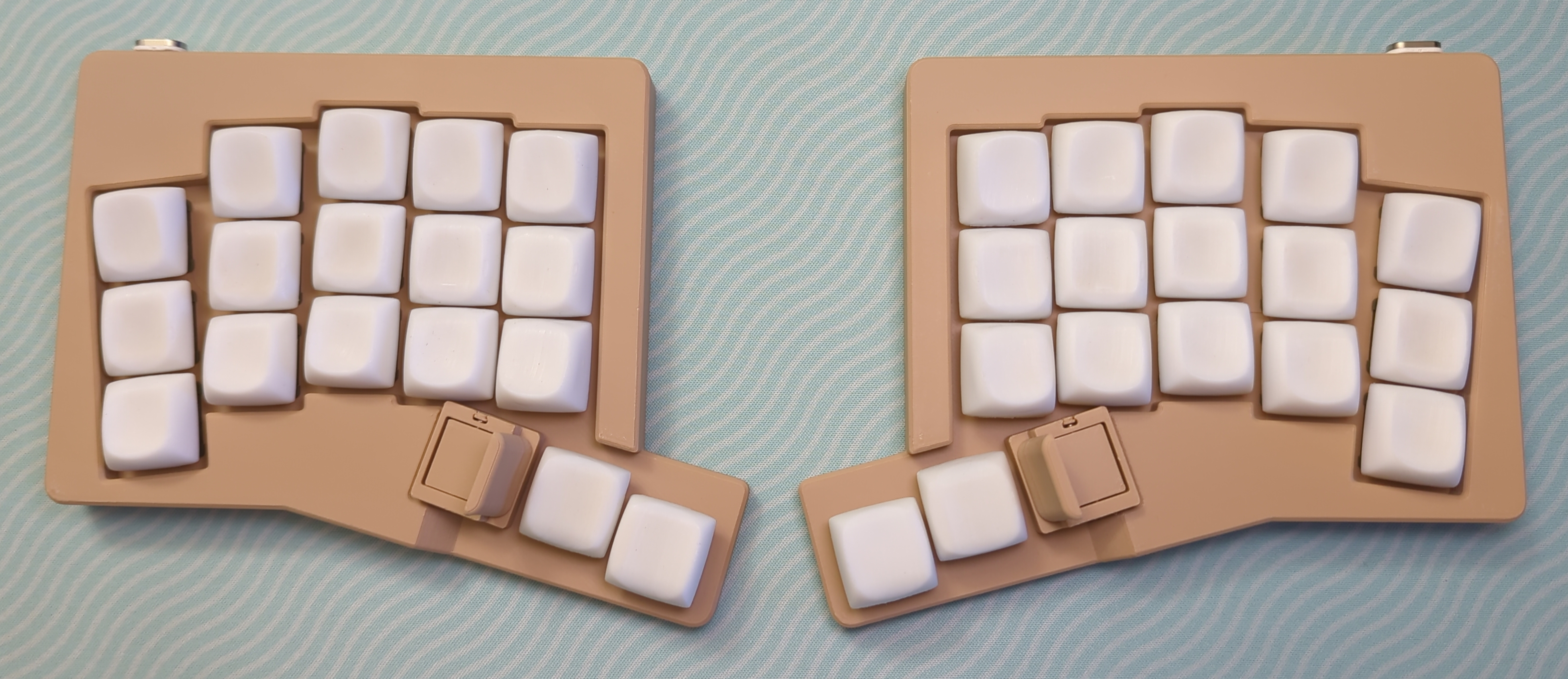
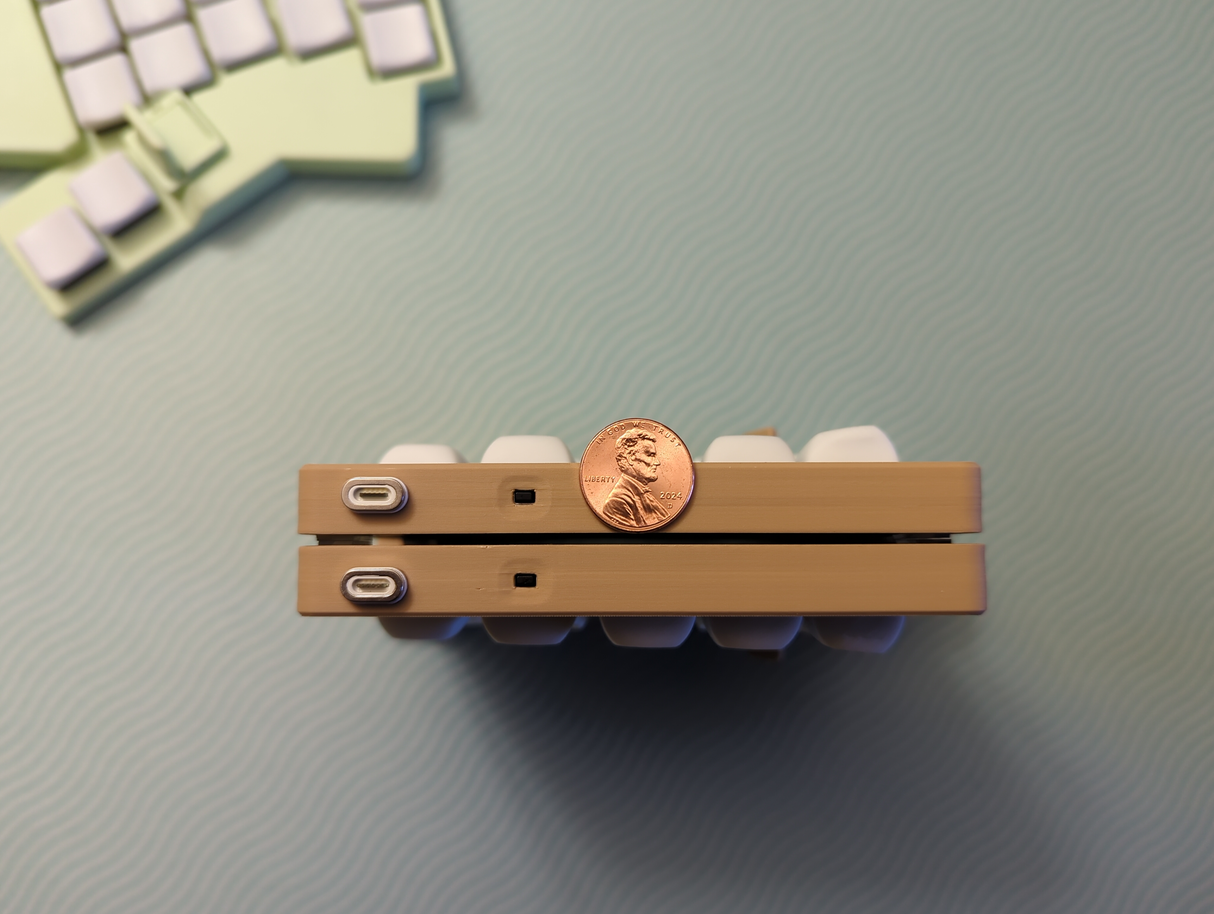
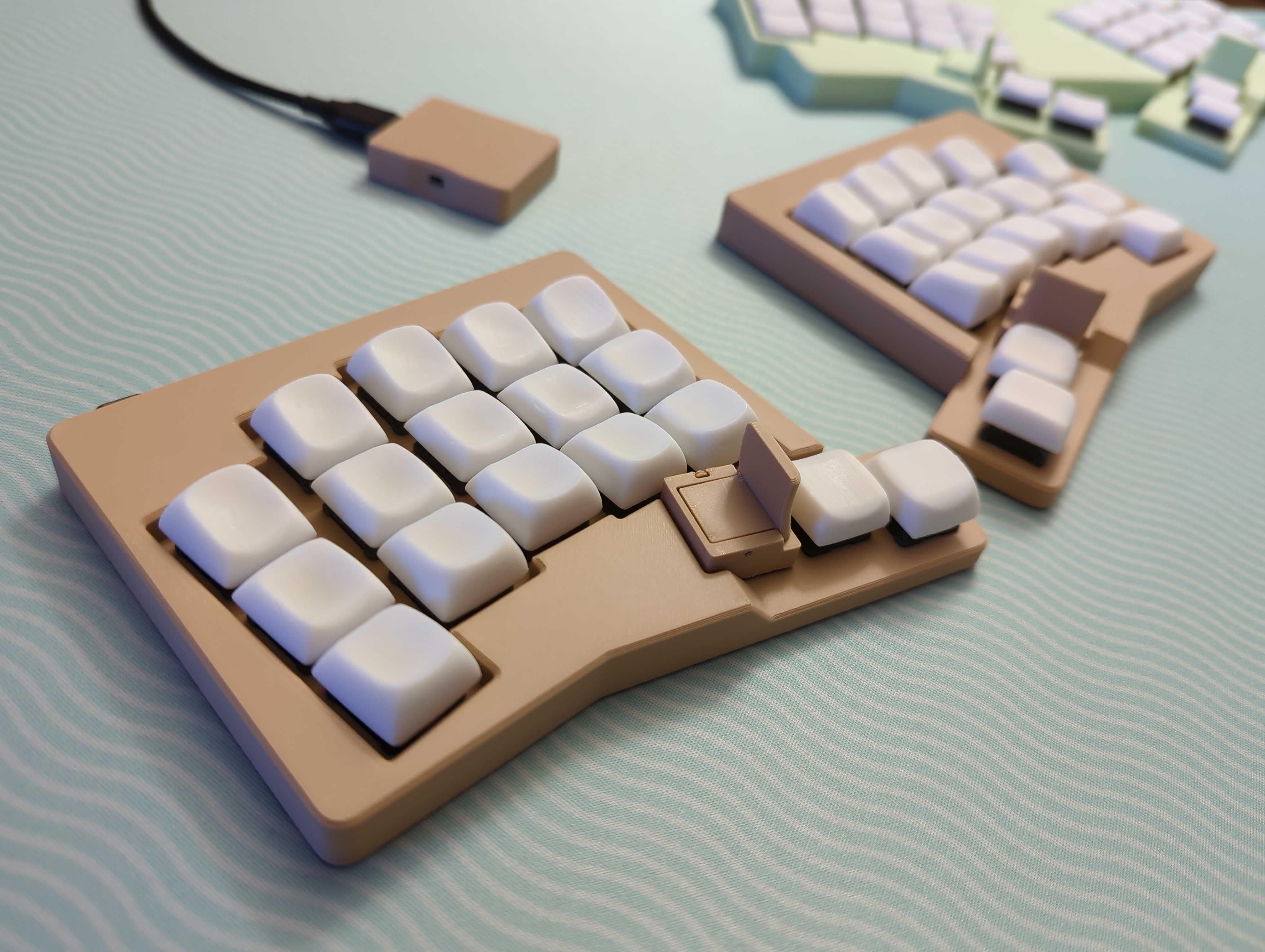
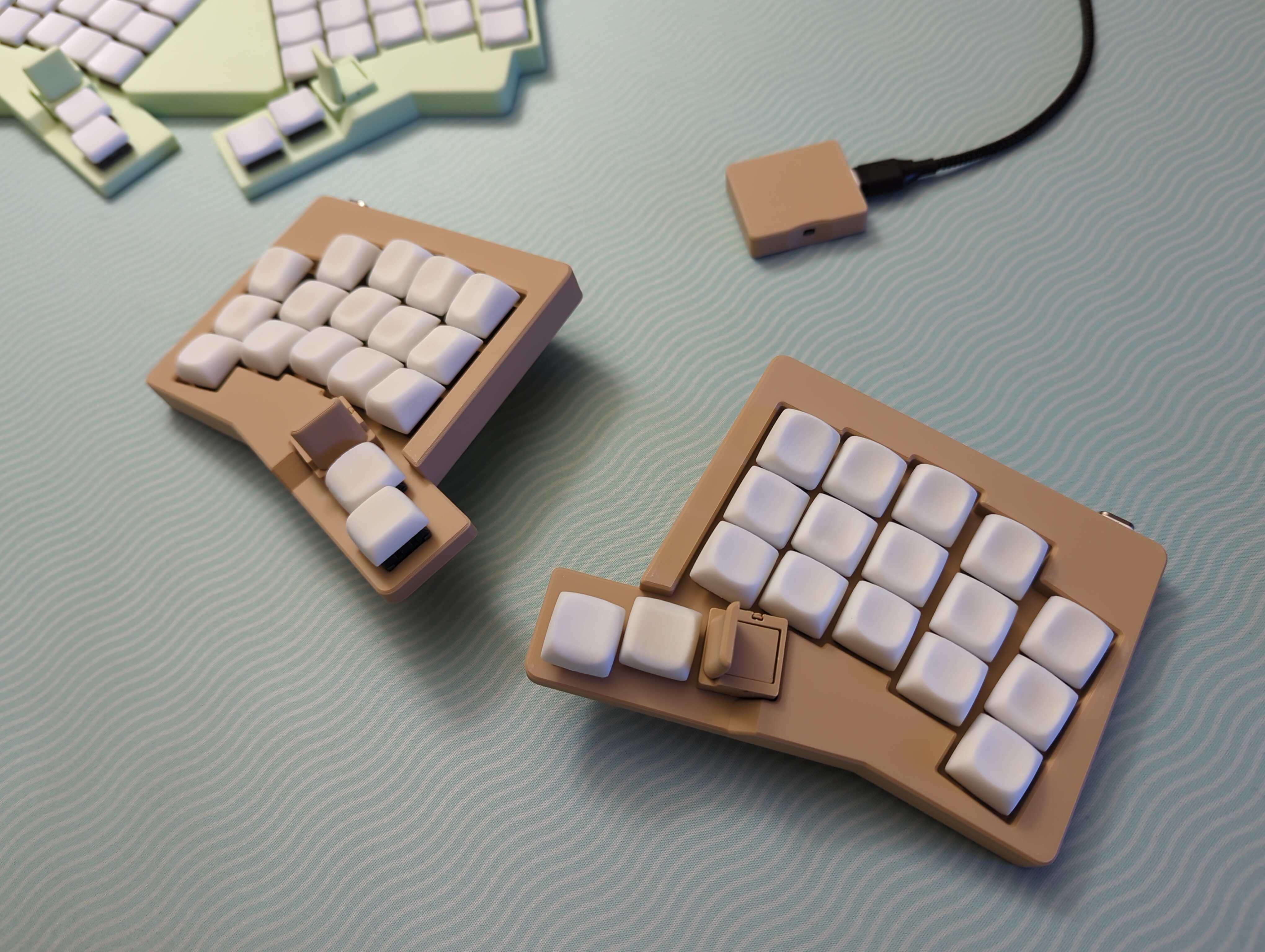
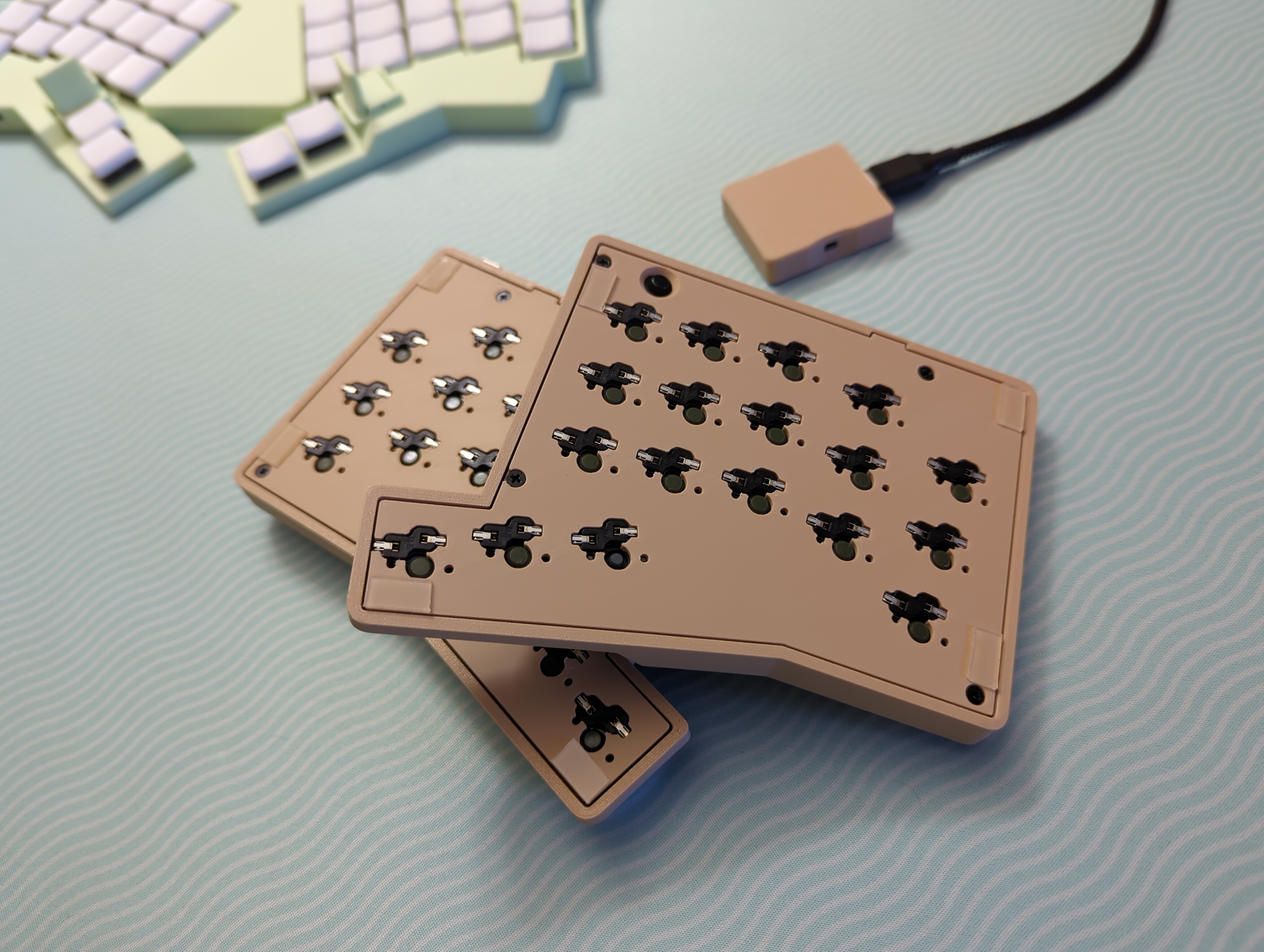
Liaison is a wireless 36-key split keyboard that leverages custom keycaps, splay, and tenting for ergonomics.
Video showcase:
Fit and layout
Typing test
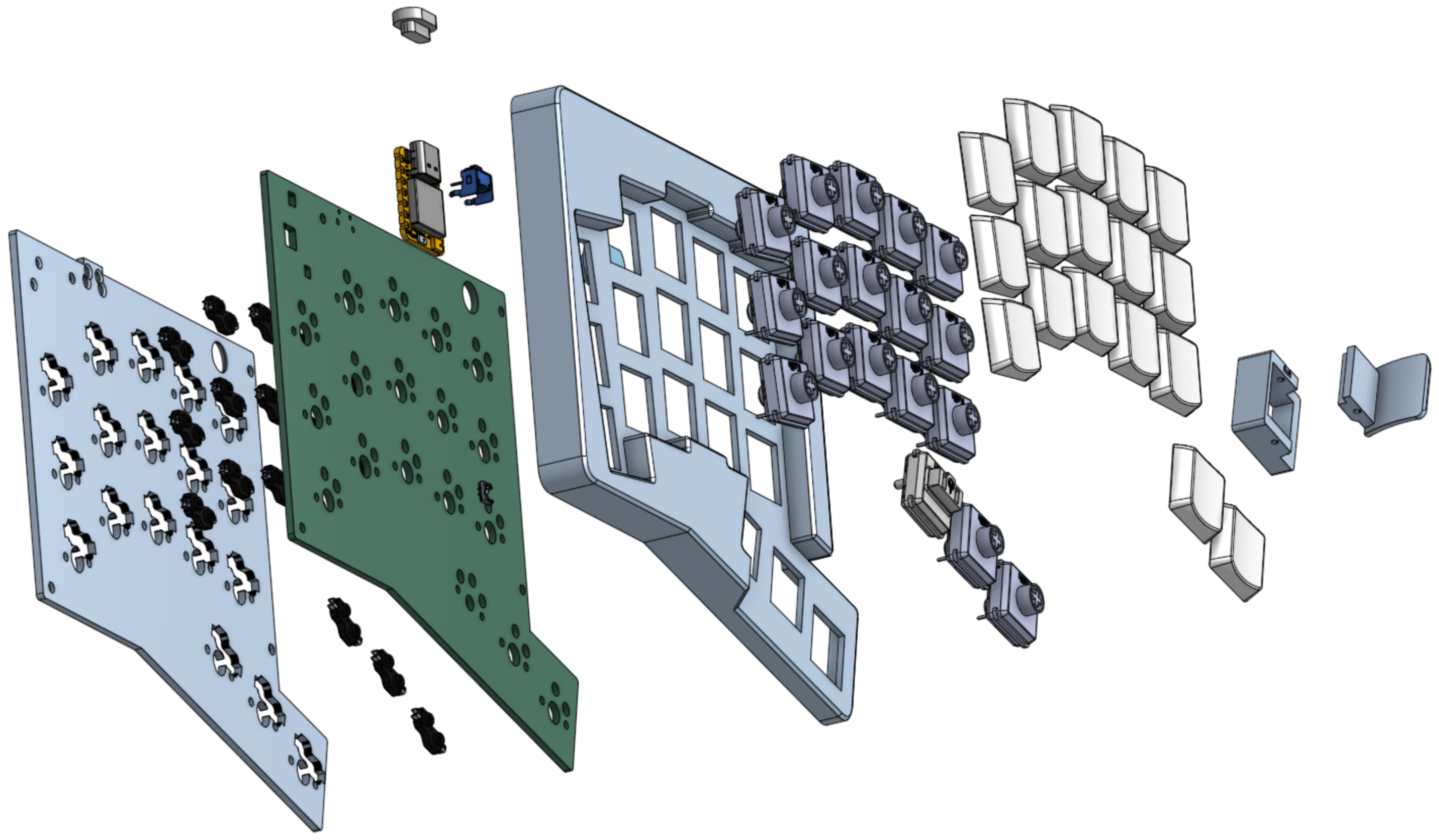
Here you can find models for the case and magsafe tenting legs.
Print 1 of each of the following:
Tenting legs (optional)
Dongle case (optional)
| Part | Quantity | Link |
|---|---|---|
| Microcontroller: Xiao nRF52840 | 1 | https://www.seeedstudio.com/Seeed-XIAO-BLE-nRF52840-p-5201.html |
| Battery: 301230 with molex pico ezmate connector | 1 | Select L0040. https://www.aliexpress.us/item/3256802674181210.html |
| Battery connector: molex pico ezmate 1x02 | 1 | Select 2P. https://www.aliexpress.us/item/3256805726980487.html |
| Power button: 1208YD | 1 | https://www.aliexpress.us/item/3256801267126259.html |
| Reset button: SKHLLCA010 | 1 | https://www.aliexpress.us/item/3256805176534062.html |
| M2 heatset inserts (OD:3.2, Height: 2-3mm) | 8 | https://www.aliexpress.us/item/3256804856964661.html |
| Switches | 36 | Your choice of choc v1 or v2. Recommended: Lofree ghost, swap springs |
| Kailh Choc PG1350 Hot Swap Sockets | 36 | https://www.aliexpress.us/item/3256803687338432.html |
| Silicone sheet for feet | 1 | https://www.amazon.com/dp/B09NW63JLC |
| Keycaps | 36 | Your choice. Recommended: low profile DES + lever keycaps |
[!NOTE] Keycap dimensions must be ≤17.85mm wide and ≤18mm deep. All standard choc keycaps will fit.
| Part | Quantity | Link |
|---|---|---|
| Magsafe puck: Vrig MG-01 | 2 | https://www.aliexpress.us/item/3256804940825578.html |
| Magsafe plate | 2 | https://www.amazon.com/dp/B09B6XGTWL |
| 1/4" thread screw ~9mm | 2 | There are cheaper sources out there, but here is a link: https://www.amazon.com/dp/B01MS60KSY |
| Magnetic USB connector/cable: Netdot Gen10 | 2 | https://www.amazon.com/dp/B07MBD3FZD |
Here you can find the liaison's ZMK module. The firmware is configured for dongle usage, however you may fork the repo if you prefer to not use a dongle.
1. Order the pcb and acquire the case
2. Order parts
3. Flash and test the microcontrollers
[!IMPORTANT] Flash your microcontrollers with firmware and test them before doing any soldering. Once the microcontrollers are soldered, they will be nearly impossible to remove without the right tools.
4. Solder components to top face of pcb
Apply flux on both the pcb pads and battery connector pins
Tin both corner pads with solder
Solder connector to the first corner by applying heat to the corner metal pin from above
Then do the same for the second corner
Apply more flux to connector pins and PCB pads
Apply solder to underside of soldering tip
Drag iron from side to side over the contacts until they are soldered. The solder will just jump to where it needs to go
Make sure to clean the flux thoroughly
5. Check your work
6. Solder components to bottom face of pcb
[!IMPORTANT] Hotswap socket orientation matters. The sockets must align with the silkscreen or the bottom case will not fit.
7. Battery installation
8. Case assembly
9. (Optional) Tenting assembly
These people and many more helped make this keyboard possible. Yall are legends.
MrZealot
Pseudoku
petejohanson
caksoylar(bravekarma)
jcmkk3
ceoloide
infused-kim
Flatfootfox
sadekbaroudi
zzeneg
joelspadin
wolfwood
claussen
Geist
rmwphd(atinyzubat)
fish
Araxia
honorless
elkepenin
reeves| Qty | Value | Footprint | References |
|---|---|---|---|
| 18 | ComboDiode | D1, D2, D3, D4, D5, D6, D7, D10, D11, D12, D13, D14, D15, D16, D17, D18 +2 | |
| 17 | 1:switch_choc_v1_v2 | S1, S2, S3, S4, S5, S6, S7, S8, S10, S11, S12, S13, S14, S15, S17, S18 +1 | |
| 3 | mounting_hole | H1, H2, H3 | |
| 1 | 1:xiao_smd_xl_cutout_minimal | MCU1 | |
| 1 | 1:molex_pico_ezmate_1x02_front | CONN1 | |
| 1 | 1:1208YD | SW1 | |
| 1 | 1:switch_choc_left_flexion | S16 | |
| 1 | icon_bat | ICON1 | |
| 1 | SKHLLCA010 | 1:SKHLLCA010 | S19 |
It measures 130 × 105 mm and has 2 copper layers, 1 mm thick.
44 parts, built around the SKHLLCA010. The full list of its parts is on this page, with links to each part's symbol and footprint where PCBKit's library has them.
From the dohn-joh/liaison repository on GitHub, at the commit this page was made from: the board is ergogen/output/pcbs/Left_render.kicad_pcb. PCBKit opens the board in the browser, with nothing to install.
Its repository publishes it under the CERN-OHL-P-2.0 licence: you may reuse it on that licence's terms (keep the author's notice, and for a copyleft licence share your changes alike).


mudmin/AnotherMaker
This is where I will store code snippets for AnotherMaker Videos

qbancoffee/imac_g3_ivad_board_init
iMac G3 IVAD board initialization with an arduino