Skip to the content
2 layers31.3 × 60.3 mmBobcat rak stack adapter, the printed circuit board in 3D

Bobcat rak stack adapter

docdailey/bobcat-300

Repurposing the Bobcat Miner 300 (G285, RK3566) for LoRa time transfer: fact-checked OS/GPIO, bare-metal Rust, GNSS populate, socket pinout, and a RAK5146 interposer

Size
31.3 × 60.3 mm
Copper layers
2
Thickness
1 mm
Parts
15
Nets
21
Pads
128
Tracks, vias
355, 176
Pours
7
Routed
Yes
KiCad
KiCad 10.0 (file 20260206)
Created
23 Oct 2026
Updated
23 Oct 2026

Overview

Bobcat rak stack adapter is an open-source printed circuit board by docdailey, from the docdailey/bobcat-300 repository on GitHub. It is a 2-layer board of 31.3 × 60.3 mm with 15 parts on 21 nets, routed with 355 tracks and 176 vias.

It is built around the PCIE-52P52H. Its parts include 8 resistors and 1 connector. It belongs with the radio and wireless and interfaces and adapters boards of this library.

Main components

1

README

README.md

bobcat-300

Repurposing the Bobcat Miner 300 (board G285-V1.0, Rockchip RK3566, mini-PCIe LoRa concentrator) from a Helium hotspot into an open, hackable LoRa node for time transfer experiments, the goal being two-way LoRa time transfer between nodes, validated against GNSS PPS.
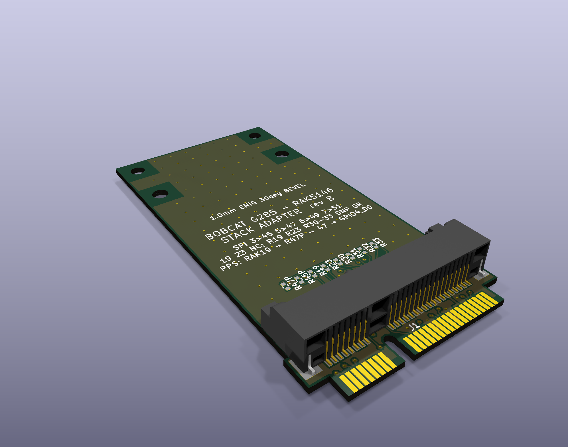
G285 → RAK5146 stack adapter

The stack adapter: plugs into the G285 concentrator socket and carries a RAK5146 (SX1303 + GPS) on top.

Everything here is fact-checked. Every claim in docs/ ends with a tag:

  • [VERIFIED: source]: checked against a primary source (code, device tree, datasheet, logic-analyzer capture, meter reading or command output, named in the tag)
  • [UNVERIFIED: origin]: from notes, community pages or inference, not yet confirmed
  • [CONTRADICTED: what disagrees]: sources disagree; both sides recorded

Each doc ends with a Contradictions & open questions section. Corrections are welcome (open an issue with evidence).

Contents

DocWhat it covers
docs/os-boot-gpio.mdArmbian on SD (eMMC untouched), boot chain and boot-script gotchas, 1.5 Mbaud debug console, Ethernet (YT8512B) and Wi-Fi quirks, radio power/reset GPIOs, SPI1, SARADC, broken DT nodes, RTC, PTP
docs/bare-metal-rust.mdBare-metal Rust image for the RK3566 (QEMU-tested), the carved-core-3 Rust PPS engine that runs on hardware, the deployed Linux time-transfer logger, measured results and lessons
docs/gnss-populate.mdThe unpopulated u-blox NEO-footprint GNSS site: pinout, parts to fit and where, antenna path, PPS routing, beep-test results, install plan, risks
docs/socket-pinout-rak5146.mdThe non-standard concentrator socket pinout (proven with a logic analyzer), why a RAK5146 reads 0xFF in a stock G285, and the interposer spec
docs/pps-uart-qerr.mdGPS PPS to the processor (R47P → GPIO4_D0) and its core-3 capture, the RAK GPS UART (pins 31/33, unmapped), and qErr sawtooth correction
stack-adapter/Rev B: Mini Card-sized stack adapter that lets a RAK5146 (SX1303 + GPS) run in the G285 socket; the RAK stacks right on top (routed, DRC-clean review release)
interposer-rev-a/Rev A breakout interposer (50 × 109.5 mm, superseded by the stack adapter)
tools/Small scripts used for the work (see below)

Key facts at a glance

  • Concentrator socket SPI (G285): SCK = 3, MISO = 5, MOSI = 6, CS = 7. A RAK2287/RAK5146-style card expects 45/47/49/51, so it cannot talk in a stock G285 without rerouting. Power (2/24/39/41/52) and ground match.
  • Radio control GPIOs (Linux sysfs numbers on the Armbian 6.18 image): 125 = GPIO3_D5 RF enable, 122 = GPIO3_D2 power, 149 = GPIO4_C5 reset. SPI1 (spi1m1) → /dev/spidev1.0.
  • Debug console: UART2 at 1,500,000 baud (not 115200).
  • Stock card: N3504S (SX1302 + 2× SX1250). SX1302 has no fine timestamp; SX1303 (e.g. RAK5146) does.
  • GNSS: an empty 24-pad u-blox NEO footprint whose TIMEPULSE pad reaches socket pin 19 through an unfitted resistor. Do not bridge it if a RAK5146 is fitted, because its GPS drives pin 19 itself.

Tools

FilePurpose
tools/reset_lgw.shRadio power/reset sequence for the G285, matching the stock firmware (used by Semtech sx1302_hal)
tools/hal-bobcat.patchsx1302_hal V2.1.0 patch: runs without the STTS751 temperature sensor the G285 lacks, and prints the chip model (SX1302 vs SX1303)
tools/pinscan.pyRead-only GPIO input scanner (reads each bank's input register via /dev/mem) to map pads to SoC pins
tools/stim.pyLogic-analyzer stimulus: SPI1 test pattern bursts plus a slow reset toggle
tools/chiploop.shRepeated chip_id reads for capturing live MISO traffic

Safety

  • Work with the stock eMMC untouched: boot Armbian from SD. Pull the card to get the stock firmware back.
  • The concentrator can transmit at up to 27 dBm. Keep an antenna or load attached, and observe your local regulations.
  • Socket tails are 0.8 mm pitch. Power off before probing with anything that can bridge pins.

Credits and references

  • Armbian image for the G285: sicXnull/Bobcat-Armbian.
  • Community pinout reference: helium-repurposed.deobfuscated.org, Devices / Bobber / Bobcat Miner 300.
  • Semtech sx1302_hal; RAKwireless RAK5146 datasheet; u-blox NEO-M8 datasheet and hardware integration manual.

License

MIT (see LICENSE), except tools/hal-bobcat.patch, which modifies Semtech's sx1302_hal and stays under Semtech's Revised BSD License.

Parts

15
QtyValueFootprintReferences
70R DNPtscircuit:resistor_res0402R19, R23, R30, R31, R32, R33, R45P
2Bobcat hold-down 2.6mmtscircuit:hole_circle_holeDiameter2.6mmMH1, MH2
2RAK standoff M2 2.4mmtscircuit:hole_circle_holeDiameter2.4mmMH3, MH4
2card edgetscircuit:PCIe_Mini_Card_edge_PCI-SIG_Mini_CEM_1_2CE1, CE2
10Rtscircuit:resistor_res0402R47P
1PCIE-52P52Htscircuit:PCIE-52P52HJ1

More from docdailey/bobcat-300

2
  • 2 layers78.6 × 70.5 mmBobcat rak stack adapter panel, the printed circuit board in 3D

    Bobcat rak stack adapter panel

    docdailey/bobcat-300

    Repurposing the Bobcat Miner 300 (G285, RK3566) for LoRa time transfer: fact-checked OS/GPIO, bare-metal Rust, GNSS populate, socket pinout, and a RAK5146 interposer

    100 parts
  • 4 layers50 × 109.5 mmBobcat rak interposer, the printed circuit board in 3D

    Bobcat rak interposer

    docdailey/bobcat-300

    Repurposing the Bobcat Miner 300 (G285, RK3566) for LoRa time transfer: fact-checked OS/GPIO, bare-metal Rust, GNSS populate, socket pinout, and a RAK5146 interposer

    46 parts

Similar boards

  • 2 layers19 × 76 mmSub, the printed circuit board in 3D

    Sub

    google/mozc-devices

    Circuit diagrams and firmware source code for Gboard DIY keyboards

    15 parts3kApache-2.0
  • 2 layers26.7 × 62.2 mmDeniseadapter, the printed circuit board in 3D

    Deniseadapter

    hoglet67/RGBtoHDMI

    Bare-metal Raspberry Pi project that provides pixel-perfect sampling of Retro Computer RGB/YUV video and conversion to HDMI

    15 parts1kGPL-3.0
  • 2 layers100 × 44 mmVideoslot, the printed circuit board in 3D

    Videoslot

    mntmn/amiga2000-gfxcard

    MNT VA2000, an Open Source Amiga 2/3/4000 Graphics Card (Zorro II/III), written in Verilog

    15 parts1k
  • 2 layers91 × 51 mmBusinessCard, the printed circuit board in 3D

    BusinessCard

    hackclub/OnBoard

    💡 Join 1,000 teenagers and make your first PCB with a $100 grant!

    15 parts915
  • 2 layers24.3 × 57.9 mmFlosspods pro flex, the printed circuit board in 3D

    Flosspods pro flex

    kenp-io/not-for-airpods-repairs

    The content of this repository is licensed under the WTFPL License. Please have a close look at the terms before using this material.

    15 parts609WTFPL
  • 2 layers20.3 × 15.2 mmL0 Load, the printed circuit board in 3D

    L0 Load

    Luos-io/luos_engine

    Open-source and real-time orchestrator for cyber-physical-systems, to easily design, test and deploy embedded applications and digital twins.

    15 parts546MIT
  • 2 layers68 × 50 mmEleLab v2 PowerFeed, the printed circuit board in 3D

    EleLab v2 PowerFeed

    Chrismettal/EleLab_v2

    Cheap DIY lab system for hobbyists and the tinkering folk

    15 parts531GPL-3.0
  • 2 layers50.8 × 35.6 mmInterface, the printed circuit board in 3D

    Interface

    harbaum/I2C-Tiny-USB

    Cheap and simple I²C to USB interface

    15 parts454

Questions

How big is the Bobcat rak stack adapter PCB?

It measures 31.3 × 60.3 mm and has 2 copper layers, 1 mm thick.

What parts does the Bobcat rak stack adapter use?

15 parts, built around the PCIE-52P52H. The full list of its parts is on this page, with links to each part's symbol and footprint where PCBKit's library has them.

Where can I download the Bobcat rak stack adapter KiCad files?

From the docdailey/bobcat-300 repository on GitHub, at the commit this page was made from: the board is stack-adapter/kicad/bobcat-rak-stack-adapter.kicad_pcb and its schematic interposer-rev-a/kicad/bobcat-rak-interposer.kicad_sch. PCBKit opens the board in the browser, with nothing to install.

Can I use the Bobcat rak stack adapter design in my own project?

Its repository states no licence, so its author keeps all rights: ask docdailey before reusing the design.