
4 layers50 × 109.5 mm
Bobcat rak interposer
docdailey/bobcat-300
Repurposing the Bobcat Miner 300 (G285, RK3566) for LoRa time transfer: fact-checked OS/GPIO, bare-metal Rust, GNSS populate, socket pinout, and a RAK5146 interposer
46 parts

 docdailey/bobcat-300
Repurposing the Bobcat Miner 300 (G285, RK3566) for LoRa time transfer: fact-checked OS/GPIO, bare-metal Rust, GNSS populate, socket pinout, and a RAK5146 interposer
Bobcat rak stack adapter panel is an open-source printed circuit board by docdailey, from the docdailey/bobcat-300 repository on GitHub. It is a 2-layer board of 78.6 × 70.5 mm with 100 parts on 42 nets, routed with 710 tracks and 352 vias.
It is built around the PCIE-52P52H. Its parts include 16 resistors and 2 connectors. It belongs with the radio and wireless and interfaces and adapters boards of this library.
Repurposing the Bobcat Miner 300 (board G285-V1.0, Rockchip RK3566, mini-PCIe LoRa concentrator) from a Helium hotspot into an open, hackable LoRa node for time transfer experiments, the goal being two-way LoRa time transfer between nodes, validated against GNSS PPS.
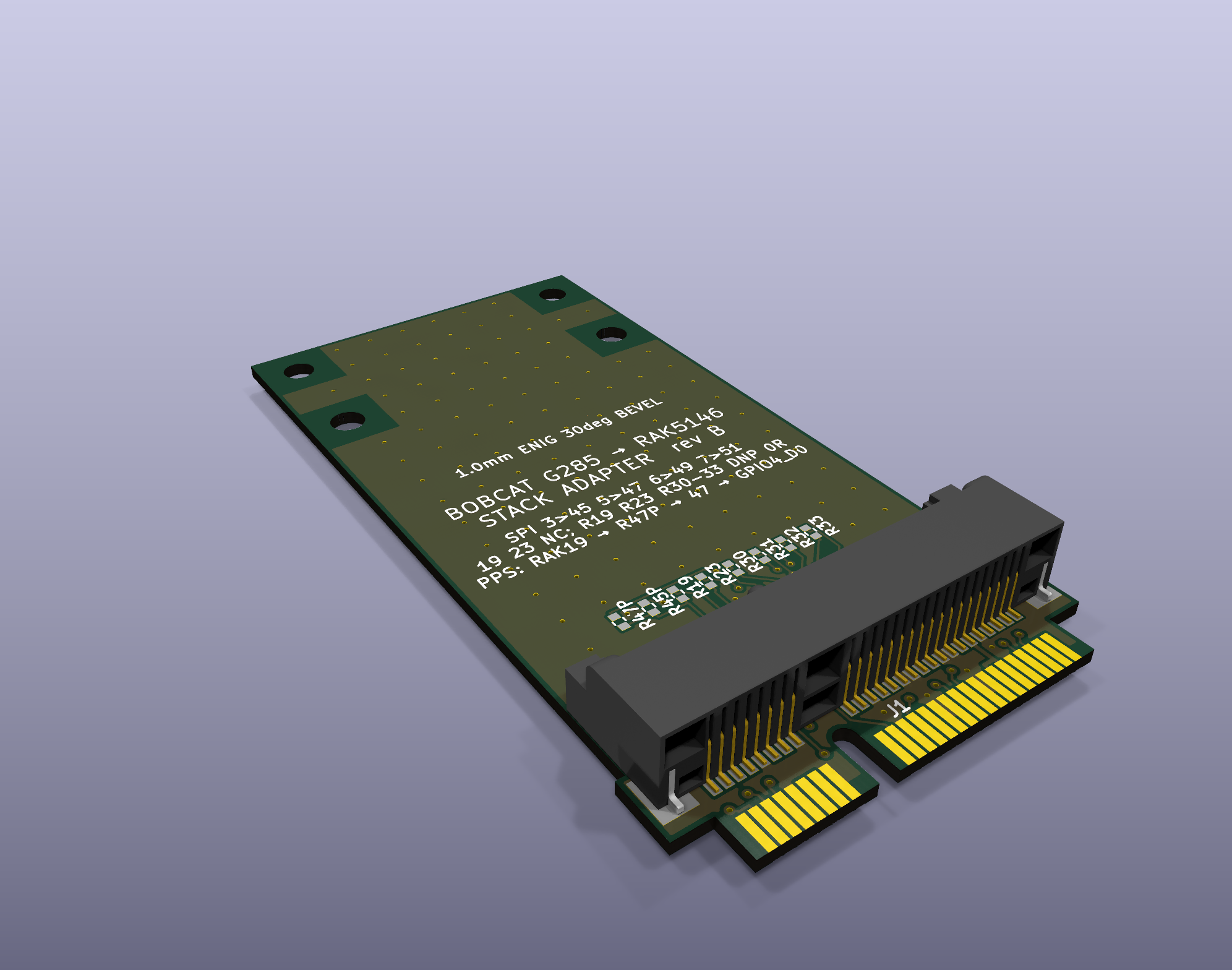
The stack adapter: plugs into the G285 concentrator socket and carries a RAK5146 (SX1303 + GPS) on top.
Everything here is fact-checked. Every claim in docs/ ends with a tag:
Each doc ends with a Contradictions & open questions section. Corrections are welcome (open an issue with evidence).
| Doc | What it covers |
|---|---|
| docs/os-boot-gpio.md | Armbian on SD (eMMC untouched), boot chain and boot-script gotchas, 1.5 Mbaud debug console, Ethernet (YT8512B) and Wi-Fi quirks, radio power/reset GPIOs, SPI1, SARADC, broken DT nodes, RTC, PTP |
| docs/bare-metal-rust.md | Bare-metal Rust image for the RK3566 (QEMU-tested), the carved-core-3 Rust PPS engine that runs on hardware, the deployed Linux time-transfer logger, measured results and lessons |
| docs/gnss-populate.md | The unpopulated u-blox NEO-footprint GNSS site: pinout, parts to fit and where, antenna path, PPS routing, beep-test results, install plan, risks |
| docs/socket-pinout-rak5146.md | The non-standard concentrator socket pinout (proven with a logic analyzer), why a RAK5146 reads 0xFF in a stock G285, and the interposer spec |
| docs/pps-uart-qerr.md | GPS PPS to the processor (R47P → GPIO4_D0) and its core-3 capture, the RAK GPS UART (pins 31/33, unmapped), and qErr sawtooth correction |
| stack-adapter/ | Rev B: Mini Card-sized stack adapter that lets a RAK5146 (SX1303 + GPS) run in the G285 socket; the RAK stacks right on top (routed, DRC-clean review release) |
| interposer-rev-a/ | Rev A breakout interposer (50 × 109.5 mm, superseded by the stack adapter) |
| tools/ | Small scripts used for the work (see below) |
spi1m1) → /dev/spidev1.0.| File | Purpose |
|---|---|
tools/reset_lgw.sh | Radio power/reset sequence for the G285, matching the stock firmware (used by Semtech sx1302_hal) |
tools/hal-bobcat.patch | sx1302_hal V2.1.0 patch: runs without the STTS751 temperature sensor the G285 lacks, and prints the chip model (SX1302 vs SX1303) |
tools/pinscan.py | Read-only GPIO input scanner (reads each bank's input register via /dev/mem) to map pads to SoC pins |
tools/stim.py | Logic-analyzer stimulus: SPI1 test pattern bursts plus a slow reset toggle |
tools/chiploop.sh | Repeated chip_id reads for capturing live MISO traffic |
sx1302_hal; RAKwireless RAK5146 datasheet; u-blox NEO-M8 datasheet and hardware integration manual.MIT (see LICENSE), except tools/hal-bobcat.patch, which modifies Semtech's sx1302_hal and stays under
Semtech's Revised BSD License.
| Qty | Value | Footprint | References |
|---|---|---|---|
| 64 | NPTH | NPTH | KiKit_MB_1_1, KiKit_MB_10_1, KiKit_MB_10_2, KiKit_MB_10_3, KiKit_MB_10_4, KiKit_MB_10_5, KiKit_MB_11_1, KiKit_MB_11_2, KiKit_MB_11_3, KiKit_MB_11_4, KiKit_MB_11_5, KiKit_MB_12_1, KiKit_MB_12_2, KiKit_MB_12_3, KiKit_MB_12_4, KiKit_MB_12_5 +48 |
| 14 | 0R DNP | tscircuit:resistor_res0402 | R19_0, R19_1, R23_0, R23_1, R30_0, R30_1, R31_0, R31_1, R32_0, R32_1, R33_0, R33_1, R45P_0, R45P_1 |
| 6 | Fiducial | Fiducial | KiKit_FID_B_1, KiKit_FID_B_2, KiKit_FID_B_3, KiKit_FID_T_1, KiKit_FID_T_2, KiKit_FID_T_3 |
| 4 | Bobcat hold-down 2.6mm | tscircuit:hole_circle_holeDiameter2.6mm | MH1_0, MH1_1, MH2_0, MH2_1 |
| 4 | RAK standoff M2 2.4mm | tscircuit:hole_circle_holeDiameter2.4mm | MH3_0, MH3_1, MH4_0, MH4_1 |
| 4 | card edge | tscircuit:PCIe_Mini_Card_edge_PCI-SIG_Mini_CEM_1_2 | CE1_0, CE1_1, CE2_0, CE2_1 |
| 2 | 0R | tscircuit:resistor_res0402 | R47P_0, R47P_1 |
| 2 | PCIE-52P52H | tscircuit:PCIE-52P52H | J1_0, J1_1 |
docdailey/bobcat-300
Repurposing the Bobcat Miner 300 (G285, RK3566) for LoRa time transfer: fact-checked OS/GPIO, bare-metal Rust, GNSS populate, socket pinout, and a RAK5146 interposer

docdailey/bobcat-300
Repurposing the Bobcat Miner 300 (G285, RK3566) for LoRa time transfer: fact-checked OS/GPIO, bare-metal Rust, GNSS populate, socket pinout, and a RAK5146 interposer

shanteacontrols/OpenDeck
A platform for building interactive control and sensing devices using MIDI and OSC built with Zephyr RTOS.

Redherring32/OpenTendo
An Open-Source HardWare (OSHW) recreation of the original 1985 front-loading NES Motherboard


vsfteam/vsf
Versaloon Software Framework -- a tiny preemptive-capable event-driven incremental software framework for embedded systems


cnlohr/cnhardware
My dumping grounds for all my kicad projects and random hardware bringup.

It measures 78.6 × 70.5 mm and has 2 copper layers, 1 mm thick.
100 parts, built around the PCIE-52P52H. The full list of its parts is on this page, with links to each part's symbol and footprint where PCBKit's library has them.
From the docdailey/bobcat-300 repository on GitHub, at the commit this page was made from: the board is stack-adapter/fab/panel/bobcat-rak-stack-adapter-panel.kicad_pcb and its schematic interposer-rev-a/kicad/bobcat-rak-interposer.kicad_sch. PCBKit opens the board in the browser, with nothing to install.
Its repository states no licence, so its author keeps all rights: ask docdailey before reusing the design.