
2 layers100 × 50 mm
 doBeschte/py.console
A gaming console based on a Raspberry Pi 5 and python games with 5 bluetooth-controllers
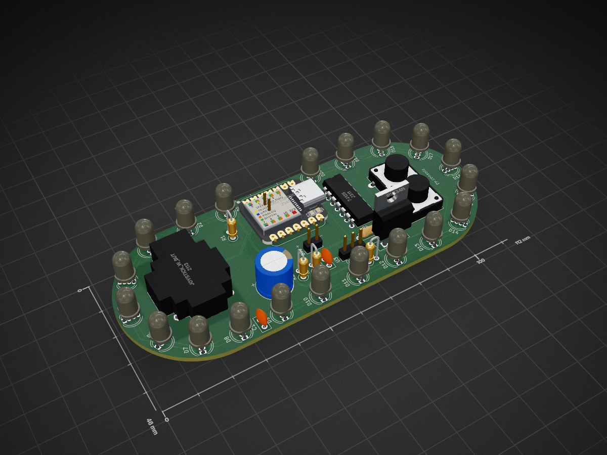
Py consoller is an open-source printed circuit board by doBeschte, from the doBeschte/py.console repository on GitHub. It is a 2-layer board of 112 × 46 mm with 37 parts on 41 nets, routed with 359 tracks and 0 vias.
It is built around the IRLZ34N. Its parts include 20 diodes, 5 resistors, 4 ICs, 3 capacitors and 2 switches. It belongs with the ESP32 and RISC-V boards of this library.
A gaming console based on a Raspberry Pi 5 and python games with 5 bluetooth-controllers I designed the 3D-printed parts in Fusion360, the schematics and the PCB in KiCAD.
The console is based on a Raspberry Pi 5. The 3D-printed housing (12cm x 12cm) includes two parts. The main part holds all the components and electronics.
The top view looks like this:
On the left side of this picture the Raspberry Pi will be mounted using four pieces that fit into its mounting holes. The HDMI-Ports and the USB-C-Ports are accessible from the back side of the console.
On the sides I designed some holes for the air outlet of the device.
On the front are two holes for a USB port and a boot push button. The USB port is connected to the USB port of the Raspberry Pi. It will be used to connect a USB stick with the .py game files. The wires of the push button are connected to the two pins next to the battery connector on the Raspberry Pi to act like the integrated button. The button has an integrated LED that is connected to GPIO13 with a resistor in series to be enabled when the device is operating. An active buzzer is connected to GPIO18 to make a sound when booting or starting a game. It is placed in the hole of the case.
The other housing part is the top cover.
It is mounted with two screws on the front and round pieces that fit into holes in the main part at the back.
I will use the Raspberry Pi active cooler that takes air through the holes in the top cover.
https://github.com/user-attachments/assets/2c3ed64f-fc42-457b-9e3d-2fc4b27291a0
This video shows how the mounting will work
The controllers are more complicated as they are smaller and include more components. I build five of them because a lot of things are shipped in five or ten, including PCBs, Joysticks, buttons, batteries etc. .
The rendering doesn't include the joystick because I don't print it by myself.
The microcontroller is a XIAO-ESP32-C3 that has BLE and a battery charger and it is small. Its USB-C port is the charging port of my controller.
At the left side is a tipical thumb joystick and at the right side two buttons. They are connected to inputs on the ESP32 and GND. Around the PCB are 20 "PL9823" LEDs. They need 5 volts which the ESP32 doesn't deliver. So, I use a little boost converter from the battery cell to five volts and a 74125 level shifter (with a 330Ω resistor) for the data. A MOSFET turnes the boost converter off when the ESP32 is in DeepSleep. Two capacitors deliver high current for the LEDs for a short time. The battery voltage is measured by splitting it in half using two resistors 1MΩ
The device is 12cm x 5cm, rounded at the sides and around 26mm thick. The case is made like the one of the console, but the cover is at the opposite side. The PCB is held between these two parts.
The main part holds the battery in the middle and the "keycaps" at the right side OF THE DEVICE.
The "keycaps" just fit into their holes and have a margin to prevent falling out.
The cover is screwed into the main case at the sides. It holds the PCB at the edges, under the joystick and under the keys for pressure, leaving a bit of space for the solder joints.
The PCB in my Renderings does not already contain all of the parts and some are just visible as pin headers:
The following picture shows the mounted PCB inside the case. It might look wrong at the sides (little space) but it isn't.
CONSOLE:
• Raspberry Pi 5, 4GB RAM - /
• Power supply for Pi 5 - /
• Raspberry Pi 5 active cooler - /
• USB-A port - /
• push button, 16mm mounting hole - /
• active buzzer, 24mm Ø - /
• 330Ω resistor - /
• microSD-card - /
TOTAL PRICE CONSOLE: / (I will buy everything by myself)
CONTROLLERS:
• 5pcs custom PCB, 112mm*46mm - 5,16€
• 5pcs Seeed Studio XIAO-ESP32-C3 - 33,33€
• 5pcs thumb joystick - 0,87€
• 10pcs silent push button, 8*8mm - 5,62€
• 10pcs LiPo battery, 30mm* 40mm* 5mm - 16,88€
• 5pcs voltage regulator - 7,50€
• 5pcs 74125 level shifter - 5,04€
• 5pcs 330Ω resistor - / (I have them)
• 10pcs 1MΩ resistor - / (also them :D )
• 10pcs 100nF capacitor - 0,87€
• 5pcs polarized capacitor - 0,87€
• 100pcs PL9823 LED - 5,50€
• 5pcs MOSFET (IRLZ44N) - 4,60€
TOTAL PRICE 5 CONTROLLERS: 85,55€
The console uses the Raspberry Pi Desktop. After booting, a menu appears. It shows python files saved on the external USB stick and uses pygame for the graphics. The idea behind this project: All of the other software are some python games on a USB stick. I can code them by myself or download them from the internet - as many as I want!
The controllers are coded in C++ and use ESP32 bleGamepad library. They use DeepSleep to be shut down by pressing the joystick for 5 seconds or by inactivity. Pressing the Joystick will wake the ESP32 up. The code includes a lot of animations for the LEDs, using fastLED library. The battery level is calculated using the measured battery voltage and a table from the web. It is sent every 20 seconds to the connected device and displayed on the LEDs when starting and if it is under 20%.
Please note that i will only buy the selected items.
| Qty | Value | Footprint | References |
|---|---|---|---|
| 20 | PL9823 | LED_THT:LED_D5.0mm-4_RGB | D1, D2, D3, D4, D5, D10, D11, D12, D13, D14, D15, D16, D17, D18, D19, D20 +4 |
| 3 | R | Resistor_THT:R_Axial_DIN0207_L6.3mm_D2.5mm_P2.54mm_Vertical | R2, R3, R5 |
| 2 | C | Capacitor_THT:C_Disc_D5.0mm_W2.5mm_P2.50mm | C1, C3 |
| 2 | SW_Push | Button_Switch_THT:SW_PUSH-12mm | SW1, SW2 |
| 1 | 330Ω | Resistor_THT:R_Axial_DIN0207_L6.3mm_D2.5mm_P2.54mm_Vertical | R1 |
| 1 | 74125 | Package_DIP:DIP-14_W7.62mm | U4 |
| 1 | Battery_Cell | Connector_PinHeader_2.54mm:PinHeader_1x02_P2.54mm_Vertical | BT1 |
| 1 | C_Polarized | Capacitor_THT:CP_Radial_D10.0mm_P5.00mm | C2 |
| 1 | Conn_01x02 | Connector_PinHeader_2.54mm:PinHeader_1x02_P2.54mm_Vertical | J1 |
| 1 | IRLZ34N | Package_TO_SOT_THT:TO-220-3_Vertical | Q1 |
| 1 | JOYSTICK_W_BUTTON | COM-09032:XDCR_COM-09032 | U2 |
| 1 | R | Resistor_THT:R_Axial_DIN0207_L6.3mm_D2.5mm_P7.62mm_Horizontal | R4 |
| 1 | XIAO ESP32C3 | Seeed Studio XIAO Series Library:XIAO-ESP32C3-DIP | U1 |
| 1 | ~ | Connector_PinHeader_2.54mm:PinHeader_1x03_P2.54mm_Vertical | U3 |
It measures 112 × 46 mm and has 2 copper layers, 1.6 mm thick.
37 parts, built around the IRLZ34N. The full list of its parts is on this page, with links to each part's symbol and footprint where PCBKit's library has them.
From the doBeschte/py.console repository on GitHub, at the commit this page was made from: the board is py_console/Hardware/controller/PCB/py_consoller.kicad_pcb and its schematic py_console/Hardware/console/py_console.kicad_sch. PCBKit opens the board in the browser, with nothing to install.
Its repository states no licence, so its author keeps all rights: ask doBeschte before reusing the design.

Hans-Beerman/Deurnode_ESP32-PoE
KiCad design Deurnode for the MakerSpace Leiden, based on the Olimex ESP32-PoE

3D-Printing-for-Microfluidics/3D_printer_control
2nd generation 3D printer control software

DavidJ-Saving-Time/watch-cleaner
So this is a very rough draft of code designed to run on an esp32 to control a watch cleaning machine see this YouTube video https://youtu.be/Opr75n8DbYY I'll be adding to this and making it easier for people to use.

destroyer796/3DWelder
An overbuilt 3D pen that will use a chc pro hotend and custom dc extruder powered by a power tool battery

grillbaer/solar-power-supply
Solar power harvesting for micro controller projects with li-Ion battery and highly efficient charge controller

volw/wifiOiler
Automatic, distance depending chain oiler for motorbikes with track recording (GPS).

aidtopia/spider_dropper
Mechanism to "drop" a spider (or other lightweight prop) for Halloween fun