Skip to the content
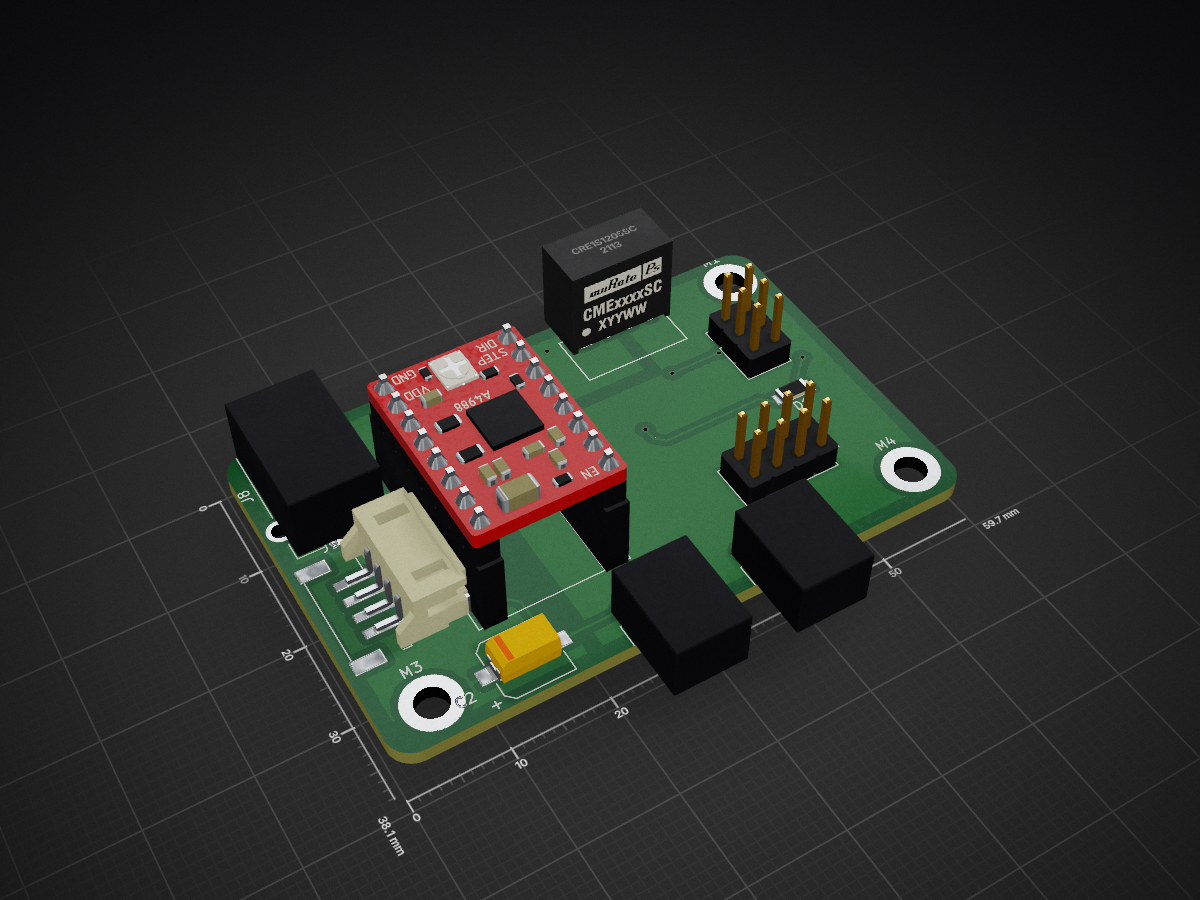
2 layers59.7 × 38.1 mmAutoWireCutterKC, the printed circuit board in 3D

This repository is for documenting the process and project of creating our own automatic wire cutter. The device will be able to take input from the user regarding wire length, options and number of wires.

Size
59.7 × 38.1 mm
Copper layers
2
Thickness
1.6 mm
Parts
20
Nets
37
Pads
101
Tracks, vias
72, 8
Pours
4
Routed
Yes
KiCad
KiCad 5 (file 20171130)
Created
27 Oct 2017
Updated
4 Oct 2018

Overview

AutoWireCutterKC is an open-source printed circuit board by dnatov, from the dnatov/AutoWire-Cutter-Stripper repository on GitHub. It is a 2-layer board of 59.7 × 38.1 mm with 20 parts on 37 nets, routed with 72 tracks and 8 vias.

It is built around the ATMEGA328P-AU and CRE1S1205SC. Its parts include 6 connectors, 4 capacitors, 3 ICs and 1 diode. It belongs with the AVR (ATmega, ATtiny) boards of this library.

Main components

2

README

README.md

AutoWire-Cutter-Stripper

This repository is for documenting the process and project of creating our own automatic wire cutter. The device will be able to take input from the user regarding wire length, options and number of wires.

The original inspiration for this project came from Reddit user "Maclsk" on the subreddit /r/specializedtools, link here: https://www.reddit.com/r/specializedtools/comments/78wd32/i_made_a_specialized_tool_for_cutting_wire/ Our goal is to create a similar device with autostripping for our workplace.
Parts

20
QtyValueFootprintReferences
4Conn_01x01_MaleMounting_Holes:MountingHole_3.2mm_M3_ISO7380_PadM1, M2, M3, M4
1100nCapacitors_SMD:C_0805_HandSolderingC1
1100uCapacitors_SMD:CP_Elec_6.3x7.7C2
11uCapacitors_SMD:C_0805_HandSolderingC5
13.3uCapacitors_Tantalum_SMD:CP_Tantalum_Case-B_EIA-3528-21_HandC6
1ATMEGA328P-AUHousings_QFP:TQFP-32_7x7mm_Pitch0.8mmU1
1Barrel_JackConnectors:Barrel_Jack_CUI_PJ-102AHJ8
1CRE1S1205SCDanaCustomLibrary:CRE1S1205SC_DC_to_DCU2
1ISPPin_Headers:Pin_Header_Straight_2x03_Pitch2.54mmJ2
1LCDPin_Headers:Pin_Header_Angled_1x03_Pitch2.54mmJ3
1LCD I/OPin_Headers:Pin_Header_Straight_2x04_Pitch2.54mmJ1
1LEDLEDs:LED_0805_HandSolderingD1
1LT1129-5.0_SOT223TO_SOT_Packages_SMD:SOT-223U3
1NSI50010YT1GDiodes_SMD:D_SOD-123I1
1Pololu_Breakout_DRV8825Modules:Pololu_Breakout-16_15.2x20.3mmA1
1ServoPin_Headers:Pin_Header_Angled_1x03_Pitch2.54mmJ5
1StepperDanaCustomLibrary:JST_PH_B4B_StressReliefCorrectJ9

Similar boards

  • 4 layers100 × 100 mmVehicleJunctionBoxMotherboard PCB, the printed circuit board in 3D

    VehicleJunctionBoxMotherboard PCB

    nsm81/VehicleJunctionBox_PCBs

    The junction box is an intermediate stage between the accumulator and inverter. It contains an HVD, a current sensor, discharge circuitry, TSAL and TSMPs.

    111 parts1
  • 4 layers100 × 46 mmSensorGrid PCB, the printed circuit board in 3D

    SensorGrid PCB

    hackwerken/SensorGrid-PCB

    89 parts
  • 4 layers163.3 × 100 mmHF phase detector, the printed circuit board in 3D

    HF phase detector

    KLFAMO/phase_detector_Artiq

    This is a phase detector designed to measure phase differences for input frequencies ranging from 0 to approximately 200 MHz. The device includes configurable frequency dividers for each input channel.

    461 parts
  • 2 layers100 × 74 mmPico CNC, the printed circuit board in 3D

    Pico CNC

    LJBlaauw/project_upgrade_3018pro_CNC

    Het project is gebaseerd op opensource tools: - Freecad (3D parametrichs CAD) - Prusa slicer (3D printables voor Z unit en moerhouders - Kicad (PCB CAD ontwerp pico CNC, firmware GRBL webbuilder) - librecad (2D CAD) -…

    87 parts
  • 2 layers81.8 × 37.6 mmBase, the printed circuit board in 3D

    Base

    meznak/helmet-signal-pcb

    Printed circuit boards for my wireless helmet signal ( https://github.com/meznak/helmet-signal )

    15 partsMIT
  • 2 layers50.5 × 128.5 mmOpenThereminV45, the printed circuit board in 3D

    OpenThereminV45

    GaudiLabs/OpenThereminV4

    Open Source Theremin Instrument

    107 parts249GPL-3.0
  • 2 layers152 × 88 mmRFBitBangSMT, the printed circuit board in 3D

    RFBitBangSMT

    profdc9/RFBitBanger

    A QRP digital transceiver created from readily available parts for off-the-grid maintenance

    271 parts222

Questions

How big is the AutoWireCutterKC PCB?

It measures 59.7 × 38.1 mm and has 2 copper layers, 1.6 mm thick.

What parts does the AutoWireCutterKC use?

20 parts, built around the ATMEGA328P-AU and CRE1S1205SC. The full list of its parts is on this page, with links to each part's symbol and footprint where PCBKit's library has them.

Where can I download the AutoWireCutterKC KiCad files?

From the dnatov/AutoWire-Cutter-Stripper repository on GitHub, at the commit this page was made from: the board is AutoWireCutterKC/AutoWireCutterKC.kicad_pcb. PCBKit opens the board in the browser, with nothing to install.

Can I use the AutoWireCutterKC design in my own project?

Its repository states no licence, so its author keeps all rights: ask dnatov before reusing the design.