
6 layers313 × 259.5 mm
Open8-vga motherboard
adham404/Open8-VGA
An 8-bit computer from 74HC logic: microcoded CPU, VGA, PS/2, on-board editor and assembler. Play it in your browser.
322 parts3MIT

This repository contains a complete KiCad project for creating a PCB that implements the circuit design of Ian Ward in his YouTube video with the title of Homebrew CPU Project
Cpu is an open-source printed circuit board by dlutz52, from the dlutz52/Homebrew-CPU-PCB repository on GitHub, published under the GPL-3.0 licence. It is a 2-layer board of 179.6 × 119 mm with 52 parts on 132 nets, routed with 907 tracks and 87 vias.
It is built around the SST39SF040-70-4C-PHE, 74LS163APC and 74LS00SC, with the 3386P-1-502LF among its other parts. Its parts include 11 resistors, 10 ICs, 7 diodes, 6 capacitors and 3 switches.


My inspiration for this PCB came from following Ian Ward's project on his web site:
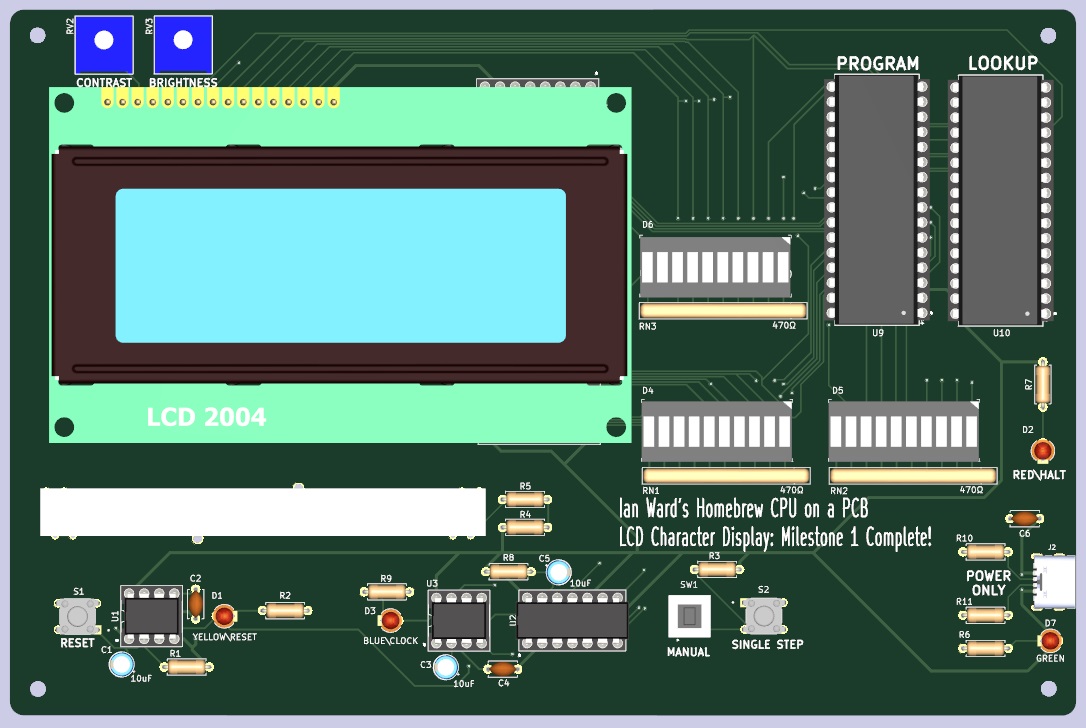
This PCB implements the LCD Character Display: Milestone 1 Complete! stage of this series of videos.
But there is more to come in the future, so checkout Ian's videos on his future plans:
Discrete Logic Rhythm Game Prototype (no CPU)
Designing a Rhythm Game: Homebrew CPU Plan Step 2
I will try to keep up with him.
PCB Front Image
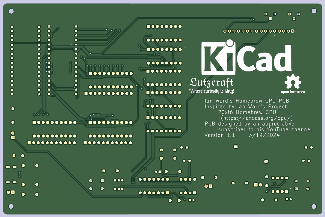
PCB Back Image
| Ref | Qty | Value | Vendor\Part # | Description |
|---|---|---|---|---|
| C1, C3, C5 | 3 | 10uF | Generic | Electrolytic capacitor |
| C2, C4, C6 | 2 | .01uF | Digikey\FG28C0G1H103JNT06 | Unpolarized capacitor |
| D1 | 1 | YELLOW\Reset | Generic | LED\3mm\Yellow |
| D2 | 1 | RED\HALT | Generic | LED\3mm\Red |
| D3 | 1 | BLUE\CLOCK | Generic | LED\3mm\Blue |
| D4, D5 | 2 | 10_SEG_LED BAR_GRAPH (Blue) | Digikey\1497-1079-5-ND | LED Bar Graph\Blue\1x10 |
| D6 | 1 | 10_SEG_LED BAR_GRAPH (Yellow) | Digikey\754-1179-5-ND | LED Bar Graph\Yellow\1x10 |
| D7 | 1 | GREEN | Generic | LED\3mm\Green |
| J1 | 1 | PinSocket_1x16_P2.54mm_Vertical | Generic | Female Pin Header\1x16\2.54mm pitch |
| J2 | 1 | UJC-HP-M-G-5-MSMT-TR | Digikey\2223-UJC-HP-M-G-5-MSMT-TRDKR-ND | Type C/20 VDC/3A/Horizontal/6 Pin/Power Only |
| R1, R3, R8 | 3 | 1Kohm | Digikey\13-MFR-25FTE52-1KCT-ND | Resistor\1Kohm\1%\1/4W\Axial |
| R2, R6, R7, R9 | 4 | 330ohm | Digikey\13-MFR-25FRF52-330RCT-ND | Resistor\330ohm\1%\1/4W\Axial |
| R4 | 1 | 220ohm | Generic | Resistor\220ohm\1%\1/4W\Axial |
| R5 | 1 | 3ohm | Generic | Resistor\3ohm\1%\1/4W\Axial |
| R10, R11 | 2 | 5.1Kohm | Digikey\13-MFR-25FTE52-5K1CT-ND | Resistor\5K1ohm\1%\1/4W\Axial |
| RN1, RN2, RN3 | 3 | 470ohm | Digikey\4609X-101-471LF-ND | Resistor Array\8 Resistors\470ohm\9SIP |
| RV1 | 1 | 10Kohm | Jameco\2276439 | Panasonic EWAQ30C15A14 Audio Slide Pot |
| RV2, RV3 | 2 | 5Kohm | Digikey\3386P-1-502LF | Trimmer Pot\5Kohms\0.5W\1/2W\Through Hole |
| SW1 | 1 | TL2230 | Digikey\EG6031-ND | Switch\Pushbutton\DPDT\Through Hole |
| S1 | 1 | REG SELECT | Digikey\450-1654-ND | Switch\Tactile\SPST-NO\0.05A\24V\Through Hole |
| S2 | 1 | ENABLE | Digikey\450-1654-ND | Switch\Tactile\SPST-NO\0.05A\24V\Through Hole |
| U1, U3 | 2 | LM555 | Digikey\LM555CNNS/NOPB-ND | 555 Timer/Oscillator\100kHz\8-PDIP |
| U2 | 1 | 74LS00 | Digikey\296-1626-ND | NAND Gate IC 4 Channel 14-PDIP |
| U4, U5, U6, U7, U8 | 5 | 74LS163 | Digikey\296-3661-5-ND | Binary Counter\4 Bit\Positive Edge\16-PDIP |
| U9, U10 | 2 | SST39SF040-70-4C-PHE | Digikey\SST39SF040-70-4C-PHE-ND | FLASH Memory\4Mbit\70ns\32-PDIP |
The LCD and its 16-pin male header are represented only with 3D models, but you need a 2004 LCD with a soldered 16-pin male header with a pitch of 2.54mm to plug into the 16 pin female header to complete this PCB. I have found the best place to get these is on eBay.
Do NOT try to use a 2004 LCD with an I2C adapter on it.
Most symbols/footprints/models are contained under the 'libraries' directory. Capacitors, resistors and LEDs use KiCad symbols/footprints/models.
KiCad 7.0.10 was used to create this PCB. KiCad 8.0.1 is out now and this project opens in that version. The newer KiCad will warn that this project was created in previous version and will be saved in a the newer format. When closing the schematic or a PCB just discard any changes. If you do not you will not be able to use KiCad 7 any more without difficulties.
Models in KiCad's 3D view will display an appropriate socket under the ICs but these can be omitted on the PCB - they are used to make it easier to replace any components should they need it in the future. The only exceptions are the sockets for the SST39SF040 FLASH chips. These chips can be changed out for different program\lookup combinations, so you do not want to solder them to the PCB. I would recommend using 32-pin sockets from Aries Electronics or something equivalent, for example, Digikey\A410AE-ND.
| Qty | Value | Footprint | References |
|---|---|---|---|
| 5 | 74LS163 | Homebrew-CPU-PCB:DIP-16_W7.62mm_Socket | U4, U5, U6, U7, U8 |
| 4 | 330Ω | Resistor_THT:R_Axial_DIN0207_L6.3mm_D2.5mm_P7.62mm_Horizontal | R2, R6, R7, R9 |
| 4 | MountingHole | MountingHole:MountingHole_2.7mm_M2.5 | H1, H2, H3, H4 |
| 3 | 0.01uF | Capacitor_THT:C_Disc_D4.7mm_W2.5mm_P5.00mm | C2, C4, C6 |
| 3 | 10uF | Capacitor_THT:CP_Radial_D4.0mm_P2.00mm | C1, C3, C5 |
| 3 | 1KΩ | Resistor_THT:R_Axial_DIN0207_L6.3mm_D2.5mm_P7.62mm_Horizontal | R1, R3, R8 |
| 3 | 470Ω | Homebrew-CPU-PCB:R_Array_SIP11 | RN1, RN2, RN3 |
| 2 | 3386P-1-502LF | Homebrew-CPU-PCB:BOURNE-3386P | RV2, RV3 |
| 2 | 5.1K | Resistor_THT:R_Axial_DIN0207_L6.3mm_D2.5mm_P7.62mm_Horizontal | R10, R11 |
| 2 | LED_BAR_GRAPH 10_SEG (Blue) | Homebrew-CPU-PCB:LED_Bar_Graph_10_SEG | D4, D5 |
| 2 | LM555 | Homebrew-CPU-PCB:DIP-8_W7.62mm_Socket | U1, U3 |
| 2 | SST39SF040-70-4C-PHE | Homebrew-CPU-PCB:PDIP32_PH_SST_MCH | U9, U10 |
| 1 | 10K | Homebrew-CPU-PCB:10K_Audio_Slide_Pot | RV1 |
| 1 | 220Ω | Resistor_THT:R_Axial_DIN0207_L6.3mm_D2.5mm_P7.62mm_Horizontal | R4 |
| 1 | 3Ω | Resistor_THT:R_Axial_DIN0207_L6.3mm_D2.5mm_P7.62mm_Horizontal | R5 |
| 1 | 74LS00 | Homebrew-CPU-PCB:DIP-14_W7.62mm_Socket | U2 |
| 1 | BLUE\CLOCK | LED_THT:LED_D3.0mm | D3 |
| 1 | CUI_UJC-HP-M-G-5-MSMT-TR | Homebrew-CPU-PCB:CUI_UJC-HP-M-G-5-MSMT-TR | J2 |
| 1 | GREEN | LED_THT:LED_D3.0mm | D7 |
| 1 | LCD 2004 Female Header | Homebrew-CPU-PCB:LCD_2004_PinSocket_1x16_P2.54mm_Vertical | J1 |
| 1 | LED_BAR_GRAPH 10_SEG (Yellow) | Homebrew-CPU-PCB:LED_Bar_Graph_10_SEG | D6 |
| 1 | LOGO | Homebrew-CPU-PCB:Lutzcraft_logo_1125DPI | G*** |
| 1 | RED\HALT | LED_THT:LED_D3.0mm | D2 |
| 1 | RESET | Homebrew-CPU-PCB:SW_1825967-1 | S1 |
| 1 | SINGLE STEP | Homebrew-CPU-PCB:SW_1825967-1 | S2 |
| 1 | TL2230 | Homebrew-CPU-PCB:TL2230EEF140 | SW1 |
| 1 | YELLOW\RESET | LED_THT:LED_D3.0mm | D1 |
The 50 most common of 52 parts.
adham404/Open8-VGA
An 8-bit computer from 74HC logic: microcoded CPU, VGA, PS/2, on-board editor and assembler. Play it in your browser.


dtatum7/WaCS-52KX
Control board upgrade for a 13.8 V 50 A linear bench power supply

timex-sinclair-projects/tspico-hardware
Status 2026-10-19: prototype 3 (v3.0-proto3, changes below). Proto1 (v3.0-proto1) was built and brought up; proto2 added its fixes (below).


jimbro1000/DIY-Video
General purpose video system for 8-bit computers using 74LS logic

It measures 179.6 × 119 mm and has 2 copper layers, 1.6 mm thick.
52 parts, built around the SST39SF040-70-4C-PHE, 74LS163APC, 74LS00SC and 3386P-1-502LF. The full list of its parts is on this page, with links to each part's symbol and footprint where PCBKit's library has them.
From the dlutz52/Homebrew-CPU-PCB repository on GitHub, at the commit this page was made from: the board is cpu.kicad_pcb and its schematic bar_graph.kicad_sch. PCBKit opens the board in the browser, with nothing to install.
Its repository publishes it under the GPL-3.0 licence: you may reuse it on that licence's terms (keep the author's notice, and for a copyleft licence share your changes alike).