2 layers133.4 × 62 mm
DIY Register Block
jimbro1000/DIY-Video
General purpose video system for 8-bit computers using 74LS logic
44 parts1

 jimbro1000/DIY-Video1
General purpose video system for 8-bit computers using 74LS logic
DIY Video is an open-source printed circuit board by jimbro1000, from the jimbro1000/DIY-Video repository on GitHub. It is a 4-layer board of 236.8 × 240.9 mm with 315 parts on 779 nets, routed with 4,507 tracks and 924 vias.
It is built around the 74LS245SC, 74LS373SC and 74LS163APC, with the CD4066BM, 74LS30PC and 74LS151PC among its other parts. Its parts include 104 ICs, 81 connectors, 71 capacitors and 11 resistors.


The DIY Video project is an attempt to define a reusable video "chip" with modular components. The concept is to limit the design to regular 74LS ICs.
The goal is a design that can be plugged into most (if not all) 8-bit computers.
The minimal design permits a system that can switch between a simple text mode and bitmap mode with a usable screen resolution of 320x200 pixels. Output is unterminated RGB that can be transformed into an appropriate format as required
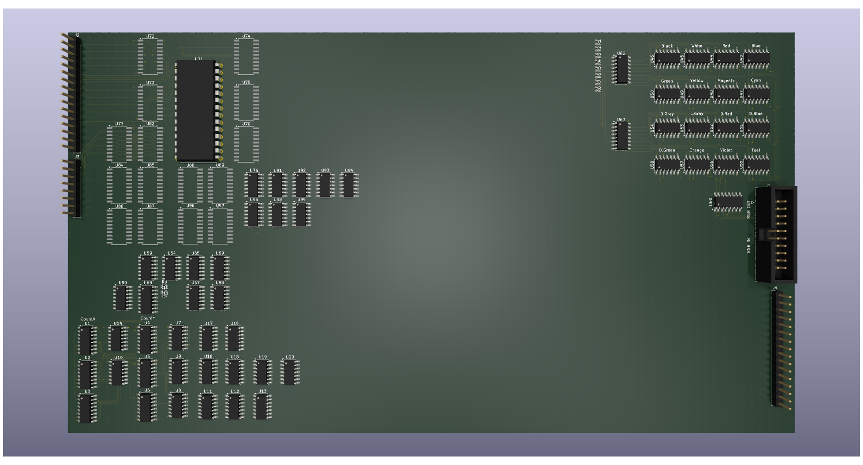
Each major component of the video system is deliberately isolated so that a change in one area should not require rework elsewhere. This rule is broken in some places but is respected as much as possible
The core of the system is a pair of counters that track the X and Y position of the "beam". These counters are then used to define the frame timing (sync and blank) and the viewport position on the screen.
The frame timing also controls what video source makes it to the output as the sync and blank phases of the signal fall under timing control.
The bitmap renderer uses the pixel counters to generate a palette index based on either a 1, 2 or 4 bit length value. The index is turned into RGB using a separate pair of modules that generate 16 distinct RGB values and a decoder that switches the RGB output between the 16 different palette options
Independently to all this is the memory controller, actually a repeated module that provisions different, parallel rendering mechanisms. From the perspective of the video system each has its own address register and can be accessed independently of the others - so the bitmap, tile and sprite data can be operated separately without impacting the timing of the other.
Externally the different blocks of memory needed to be mapped into the hosts address space. To facilitate this the different memory blocks are first selected by a device select signal and are then (optionally) paged to ease the host burden.
This approach makes the internal address very wide - each memory block is a maximum of 32K and with distinct address buses and data buses the burden for the video system is high but the length and distribution of those buses can be minimised leaving just the palette values as the the interconnect rather than wide data and address buses
The current design respects five different addressable sub-devices
Bitmap memory
Tile memory
Sprite memory
Font generator
Control registers
Only the bitmap and control registers are currently implemented.
The font generator in initial design iterations will be a simple eprom that does not require external addressing
The initial design stage is to define the hardware and interfaces, the broad timing requirements and what modules are dependent. The goal is to achieve a design that can be tested in self-contained modules, that together can implement a basic bitmap based video generator.
The initial design will be verified and refined to prove that the modules work. No attempt to integrate the modules will be attempted at this stage. Signal and power requirements will be added to the design
Modules will be implemented as independent PCBs to be re-verified. A backplane to integrate the modules will be needed with scope to extend the design to include other sub-systems
This is the first opportunity to integrate the entire set of modules defined. To provide a usable display that can be verified the system will also need to be integrated with a host computer to drive the video memory content
This project is licensed under CC BY-SA 4.0 https://creativecommons.org/licenses/by-sa/4.0/
| Qty | Value | Footprint | References |
|---|---|---|---|
| 70 | 10nF | Capacitor_SMD:C_0603_1608Metric | C1, C2, C10, C11, C12, C13, C14, C15, C16, C17, C18, C19, C20, C21, C22, C23 +54 |
| 48 | NetTie_2 | Library:NetTie-2_SMD_Pad0.4mm | NT1, NT2, NT10, NT11, NT12, NT13, NT14, NT15, NT16, NT17, NT18, NT19, NT20, NT21, NT22, NT23 +32 |
| 16 | 74LS163 | Package_SO:SOIC-16_3.9x9.9mm_P1.27mm | U1, U2, U3, U4, U5, U6, U21, U23, U26, U28, U31, U78, U79, U80, U81, U102 |
| 16 | CD4066BM | Package_SO:SO-14_3.9x8.65mm_P1.27mm | U43, U44, U45, U46, U47, U48, U49, U50, U51, U52, U53, U54, U55, U56, U57, U58 |
| 12 | 74LS30 | Package_SO:SO-14_3.9x8.65mm_P1.27mm | U7, U10, U12, U15, U17, U20, U64, U69, U111, U112, U113, U129 |
| 8 | Power | Connector_PinSocket_2.54mm:PinSocket_1x04_P2.54mm_Vertical | J43, J44, J55, J60, J74, J77, J92, J94 |
| 8 | Power and Clock | Connector_PinSocket_2.54mm:PinSocket_1x04_P2.54mm_Vertical | J11, J16, J45, J52, J81, J86, J102, J103 |
| 8 | Triggers | Connector_PinSocket_2.54mm:PinSocket_1x04_P2.54mm_Vertical | J17, J46, J51, J62, J73, J85, J100, J104 |
| 7 | 74LS151 | Package_SO:SOIC-16_3.9x9.9mm_P1.27mm | U33, U34, U35, U36, U37, U38, U39 |
| 6 | 74LS244 | Package_SO:SO-20_5.3x12.6mm_P1.27mm | U72, U73, U74, U75, U77, U82 |
| 6 | OpMode | Connector_PinSocket_2.54mm:PinSocket_1x04_P2.54mm_Vertical | J18, J47, J48, J80, J101, J105 |
| 6 | posX | Connector_PinSocket_2.54mm:PinSocket_1x10_P2.54mm_Vertical | J5, J8, J12, J87, J90, J95 |
| 6 | posY | Connector_PinSocket_2.54mm:PinSocket_1x10_P2.54mm_Vertical | J6, J9, J13, J88, J91, J96 |
| 5 | 74LS00 | Package_SO:SO-14_3.9x8.65mm_P1.27mm | U11, U18, U59, U66, U114 |
| 5 | 74LS04 | Package_SO:SOIC-14_3.9x8.7mm_P1.27mm | U103, U118, U127, U128, U136 |
| 5 | 74LS138 | Package_SO:SOIC-16_3.9x9.9mm_P1.27mm | U32, U42, U62, U63, U105 |
| 4 | 74LS253 | Package_SO:SOIC-16_3.9x9.9mm_P1.27mm | U22, U24, U27, U29 |
| 4 | BDBus | Connector_PinHeader_2.54mm:PinHeader_1x08_P2.54mm_Vertical | J53, J54, J76, J79 |
| 4 | BitmapAddress | Connector_PinHeader_2.54mm:PinHeader_1x16_P2.54mm_Vertical | J57, J58, J71, J78 |
| 3 | 100R | Resistor_SMD:R_0402_1005Metric_Pad0.72x0.64mm_HandSolder | R1, R3, R8 |
| 3 | 4K7 | Resistor_SMD:R_0402_1005Metric_Pad0.72x0.64mm_HandSolder | R9, R10, R11 |
| 3 | 74LS04 | Package_SO:SO-14_3.9x8.65mm_P1.27mm | U8, U14, U76 |
| 3 | 74LS08 | Package_SO:SO-14_3.9x8.65mm_P1.27mm | U83, U90, U110 |
| 3 | 74LS20 | Package_SO:SO-14_3.9x8.65mm_P1.27mm | U13, U16, U65 |
| 3 | 74LS32 | Package_SO:SO-14_3.9x8.65mm_P1.27mm | U9, U19, U115 |
| 3 | Host Address Bus | Connector_PinHeader_2.54mm:PinHeader_1x16_P2.54mm_Vertical | J2, J3, J84 |
| 3 | XDBus | Connector_PinHeader_2.54mm:PinHeader_1x08_P2.54mm_Vertical | J56, J75, J99 |
| 2 | 200R | Resistor_SMD:R_0402_1005Metric_Pad0.72x0.64mm_HandSolder | R2, R7 |
| 2 | 74LS08 | Package_SO:SOIC-14_3.9x8.7mm_P1.27mm | U119, U137 |
| 2 | 74LS153 | Package_SO:SOIC-16_3.9x9.9mm_P1.27mm | U40, U41 |
| 2 | 74LS32 | Package_SO:SOIC-14_3.9x8.7mm_P1.27mm | U25, U106 |
| 2 | 74LS374 | Package_SO:SO-20_5.3x12.6mm_P1.27mm | U100, U101 |
| 2 | Default Palette | Connector_PinSocket_2.54mm:PinSocket_1x04_P2.54mm_Vertical | J49, J82 |
| 2 | Output Palette | Connector_PinSocket_2.54mm:PinSocket_1x04_P2.54mm_Vertical | J50, J83 |
| 2 | PosResets | Connector_PinSocket_2.54mm:PinSocket_1x04_P2.54mm_Vertical | J10, J89 |
| 2 | RowCountControl | Connector_PinHeader_2.54mm:PinHeader_1x08_P2.54mm_Vertical | J61, J72 |
| 2 | TimingTriggers | Connector_PinSocket_2.54mm:PinSocket_1x06_P2.54mm_Vertical | J14, J97 |
| 2 | ViewportOutput | Connector_PinSocket_2.54mm:PinSocket_1x06_P2.54mm_Vertical | J15, J98 |
| 2 | ViewportTriggers | Connector_PinSocket_2.54mm:PinSocket_1x06_P2.54mm_Vertical | J7, J93 |
| 1 | 180R | Resistor_SMD:R_0402_1005Metric_Pad0.72x0.64mm_HandSolder | R5 |
| 1 | 4.7uF | Capacitor_SMD:CP_Elec_4x3 | C71 |
| 1 | 4053 | Package_SO:SOIC-16_3.9x9.9mm_P1.27mm | U60 |
| 1 | 50R | Resistor_SMD:R_0402_1005Metric_Pad0.72x0.64mm_HandSolder | R6 |
| 1 | 74ALS138 | Package_SO:SOIC-16_3.9x9.9mm_P1.27mm | U91 |
| 1 | 74LS148 | Package_SO:SOIC-16_3.9x9.9mm_P1.27mm | U68 |
| 1 | 74LS21 | Package_SO:SO-14_3.9x8.65mm_P1.27mm | U61 |
| 1 | 74LS21 | Package_SO:SOIC-14_3.9x8.7mm_P1.27mm | U104 |
| 1 | 74LS245 | Package_SO:SO-20_5.3x12.6mm_P1.27mm | U70 |
| 1 | 74LS373 | Package_SO:SO-20_5.3x12.6mm_P1.27mm | U30 |
| 1 | 75R | Resistor_SMD:R_0402_1005Metric_Pad0.72x0.64mm_HandSolder | R4 |
| 1 | CY62256-70PC | Package_DIP:DIP-28_W15.24mm | U71 |
| 1 | Control | Connector_PinHeader_2.54mm:PinHeader_1x08_P2.54mm_Vertical | J59 |
| 1 | Host Control Bus | Connector_PinHeader_2.54mm:PinHeader_1x16_P2.54mm_Vertical | J4 |
| 1 | Reg0 | Connector_PinHeader_2.54mm:PinHeader_1x08_P2.54mm_Vertical | J63 |
| 1 | Reg1 | Connector_PinHeader_2.54mm:PinHeader_1x08_P2.54mm_Vertical | J64 |
| 1 | Reg2 | Connector_PinHeader_2.54mm:PinHeader_1x08_P2.54mm_Vertical | J65 |
| 1 | Reg3 | Connector_PinHeader_2.54mm:PinHeader_1x08_P2.54mm_Vertical | J66 |
| 1 | Reg4 | Connector_PinHeader_2.54mm:PinHeader_1x08_P2.54mm_Vertical | J67 |
| 1 | Reg5 | Connector_PinHeader_2.54mm:PinHeader_1x08_P2.54mm_Vertical | J68 |
| 1 | Reg6 | Connector_PinHeader_2.54mm:PinHeader_1x08_P2.54mm_Vertical | J69 |
| 1 | Reg7 | Connector_PinHeader_2.54mm:PinHeader_1x08_P2.54mm_Vertical | J70 |
| 1 | VIDEO IO | Connector_IDC:IDC-Header_2x10_P2.54mm_Vertical | J1 |
jimbro1000/DIY-Video
General purpose video system for 8-bit computers using 74LS logic

jimbro1000/DIY-Video
General purpose video system for 8-bit computers using 74LS logic


felipesanches/Itautec_I7000_KICAD
Esquemáticos do computador Itautec I-7000 G desenhados a partir de inspeção do circuito das PCBs


fortinsylvain/MyCpu
Home brew CPU Hardware with 1-bit ALU implementation using 74LSxx, a micro-code and assembler coded in C#.

RichCini/LomasBoards
Small repository of files/data related to Lomas Data Products S-100 boards.
It measures 236.8 × 240.9 mm and has 4 copper layers, 1.6 mm thick.
315 parts, built around the 74LS245SC, 74LS373SC, 74LS163APC and CD4066BM. The full list of its parts is on this page, with links to each part's symbol and footprint where PCBKit's library has them.
From the jimbro1000/DIY-Video repository on GitHub, at the commit this page was made from: the board is DIY-Video.kicad_pcb and its schematic AddressReguster.kicad_sch. PCBKit opens the board in the browser, with nothing to install.
Its repository states no licence, so its author keeps all rights: ask jimbro1000 before reusing the design.