2 layers364 × 203 mm
 djtersteegc/Tandy-Color-Computer-Multi-Pak16
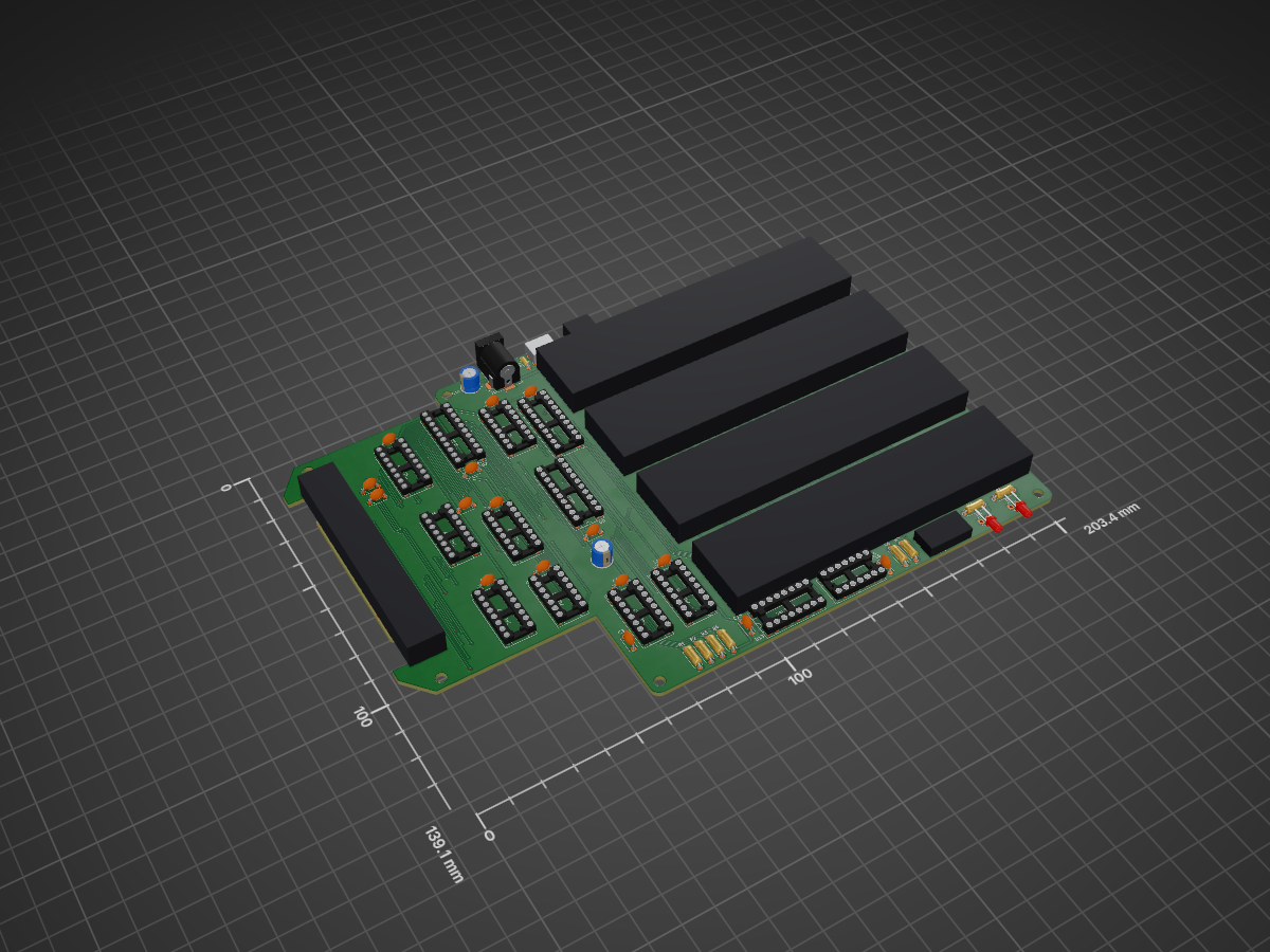
Respin of the Tandy 26-3024 Multi-Pak (MPI) for the DIY builder.
Tandy Color Computer Multi Pak is an open-source printed circuit board by djtersteegc, from the djtersteegc/Tandy-Color-Computer-Multi-Pak repository on GitHub, published under the MIT licence. It is a 2-layer board of 203.4 × 139.1 mm with 70 parts on 135 nets, routed with 1,330 tracks and 217 vias.
It is built around the 74LS367PC, 74LS245SC and AMS1117-5.0, with the 74LS139PC, 74LS153DC and 74LS30PC among its other parts. Its parts include 22 capacitors, 15 ICs, 10 resistors, 8 connectors and 2 diodes. It belongs with the FPGA and CPLD boards of this library.


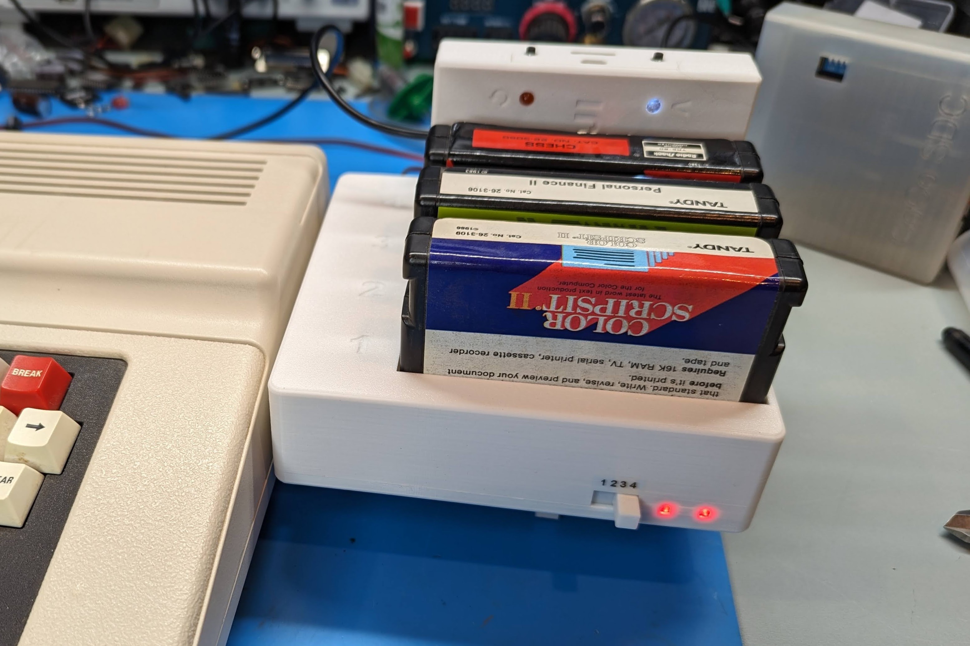
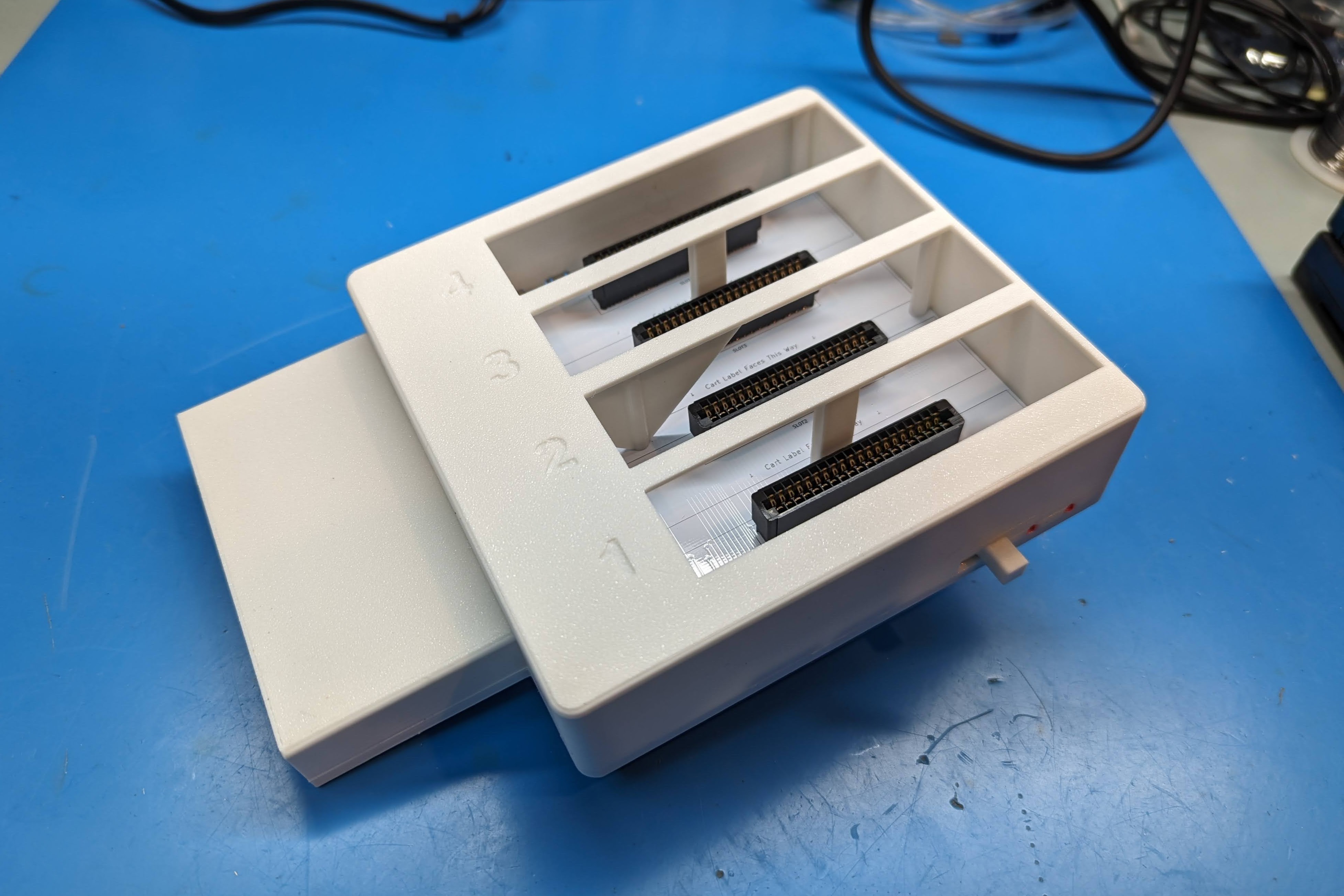
Inspired by the work of TheLittleEngineers, this is my respin of the Tandy 26-3024 Multi-Pak (MPI). It's targeted at the DIY builder so the schematic is pretty much straight out of the Tandy service manual with all THT parts, minus the power section (more on that later). The board size has been reduced as much as possible, and I added two LED's to indicate power to the MPI and Coco to minimize accidental unplugging when still powered up. The cart slots are numbered one to four, front to back, like a real MPI, but are rotated 90 degrees so the cart labels face forward. This was mainly done to better suit devices like the Coco Fujinet that have indicator LED's on the top of the cart and I saw Ed has done the same with his MPI variants.
For power you have a couple of different options. You can power directly via an external 5V PSU via either a barrel jack, USB-C, or MicroUSB ports. Or you can use a 7.5V PSU into the barrel jack and a pair of AMS1117 5V VRM's will split the power load between slots 1/2 and 3/4. For +12V and -12V there are solder jumpers on the back to take that from the Coco1 cartridge port, but no options to provide those voltages on a Coco2 or 3.
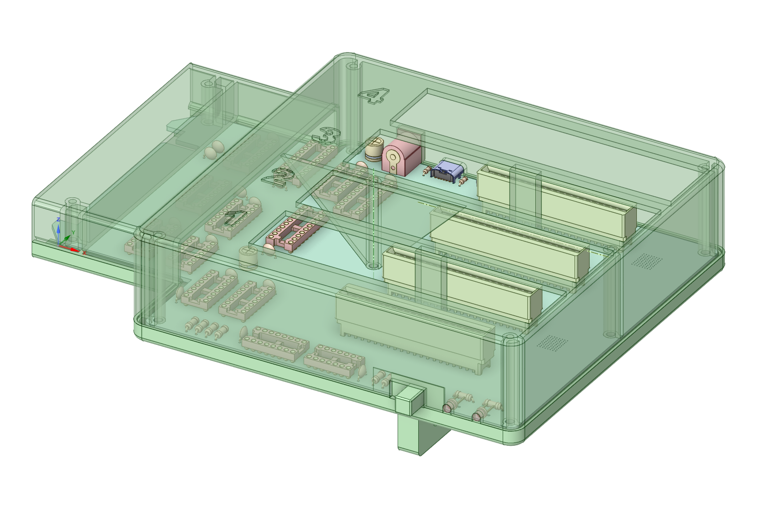
The case is a kickstand design to save on filament costs and printing time, but does have a 35mm tall top cover to better support the carts. There are also two different top designs, one that is mostly open from the cart slots to the board, and another that is fully shrouded, but uses almost double the filament. I personally haven't printed the latter option yet.
iBOM - https://djtersteegc.github.io/Tandy-Color-Computer-Multi-Pak/ibom.html
Google Sheet with some AliExpress links - https://docs.google.com/spreadsheets/d/16bxERXJ9wRitJPs6XrFosqCZR3fNDdbd6zl7ltthO44/edit?usp=sharing
I tend the buy most everything from China, either AliExpress of UTSource (for logic). For power, first figure out how you want to power the board and then pick the correct optional parts. I'm assuming everyone will install the barrel jack, either for direct 5V or to feed 7.5V into the VRM's.
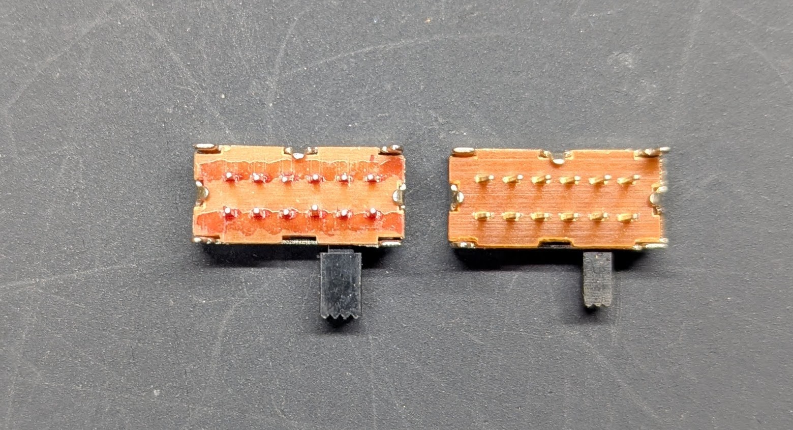
The original switches I ordered from AliExpress had a 5mm high handle that was 3mm thick. That same listing is now for a 4mm high handle model which is only 2mm thick. Looking at other listings, even the ones that still show the thicker handle appear to be sending out the shorter and thinner handled model based on review pictures posted.
There are now two STL's for the switch depending on which model you get. MPI Switch.stl is for the original taller/thicker one, and MPI Switch Small Handle.stl for the shorter/thinner one.
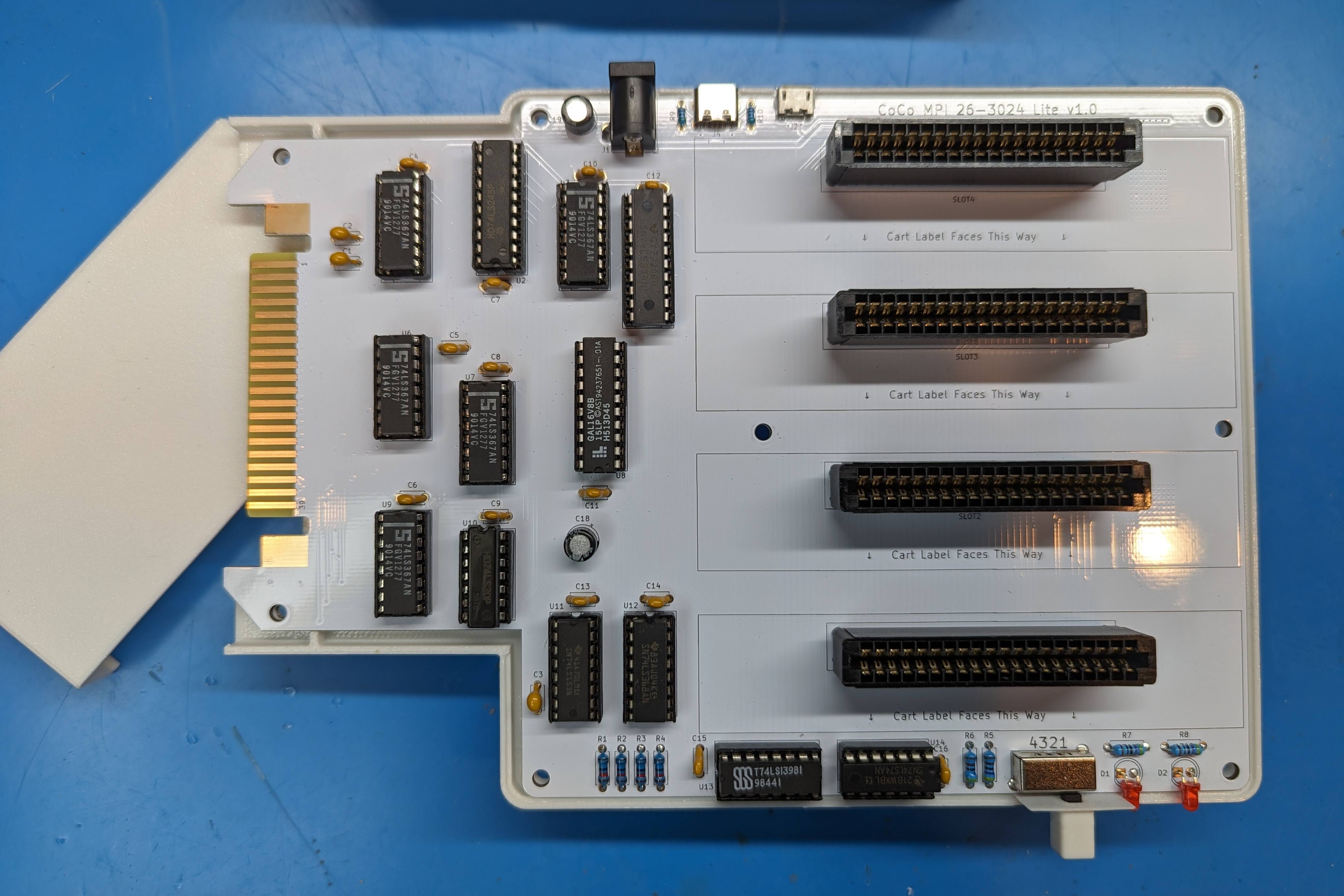
U8 is a standard GAL16V8. The programming file is available in the GAL directory. This should be the newer version that is compatible with the Coco3, but I'm unable to verify since I only have 1's and 2's to test with currently.
| Part | Filament |
|---|---|
| MPI Top.stl | 75g |
| MPI Bottom.stl | 62g |
| MPI Cart Top.stl | 20g |
| MPI Foot.stl | 12g |
| MPI Switch.stl | 1g |
| MPI Top Full Shroud.stl | 137g |
First screw the foot/kickstand to the bottom of the case with four M3x10mm button head or countersunk head screws.
Then place the PCB, slide on the printed switch handle extender, place the cart top piece and then the larger top cover. Flip over and assemble with eight M3x10mm to 14mm countersunk screws.
Gerbers are available is you want to run your own batch. I would recommend ENIG (gold) finish since this is plugging into your cart edge connector. Otherwise if you are in the US hit my up on the Coco or FujiNet Discord (hideehoo is my username there) and if I have any extras I can drop one in the mail for $15 shipped.
1.0 - Assembled and tested. Initial batch of PCB's had produced had an incorrect switch footprint that required trimming of the locating tabs and the silkscreen with the slot numbering is reversed. That has been corrected in the version 1.0 design files and gerbers in the intial upload to this repo.
| Qty | Value | Footprint | References |
|---|---|---|---|
| 13 | 0.1uF | Capacitor_THT:C_Disc_D4.7mm_W2.5mm_P5.00mm | C4, C5, C6, C7, C8, C9, C10, C11, C12, C13, C14, C15, C16 |
| 8 | MountingHole | MountingHole:MountingHole_3.2mm_M3 | H1, H2, H3, H4, H5, H6, H7, H8 |
| 5 | 74LS367 | Package_DIP:DIP-16_W7.62mm_Socket | U1, U3, U6, U7, U9 |
| 4 | 10K | Resistor_THT:R_Axial_DIN0207_L6.3mm_D2.5mm_P7.62mm_Horizontal | R1, R2, R3, R4 |
| 4 | 22uf 10V | Capacitor_Tantalum_SMD:CP_EIA-3528-12_Kemet-T_Pad1.50x2.35mm_HandSolder | C17, C20, C21, C22 |
| 2 | 100uF 16V | Capacitor_THT:CP_Radial_D6.3mm_P2.50mm | C18, C19 |
| 2 | 470R | Resistor_THT:R_Axial_DIN0207_L6.3mm_D2.5mm_P7.62mm_Horizontal | R7, R8 |
| 2 | 4K7 | Resistor_THT:R_Axial_DIN0207_L6.3mm_D2.5mm_P7.62mm_Horizontal | R5, R6 |
| 2 | 5.1K | Resistor_THT:R_Axial_DIN0204_L3.6mm_D1.6mm_P5.08mm_Horizontal | R9, R10 |
| 2 | 68pF | Capacitor_THT:C_Disc_D4.7mm_W2.5mm_P5.00mm | C1, C2 |
| 2 | AMS1117-5.0 | Tersteeg:SOT-223-3_TabPin2_Ext_Thermal | U15, U16 |
| 2 | LED | LED_THT:LED_D3.0mm | D1, D2 |
| 2 | Plug / Reg | Jumper:SolderJumper-3_P1.3mm_Open_Pad1.0x1.5mm_NumberLabels | JP1, JP2 |
| 1 | +12V | Jumper:SolderJumper-2_P1.3mm_Open_RoundedPad1.0x1.5mm | JP3 |
| 1 | -12V | Jumper:SolderJumper-2_P1.3mm_Open_RoundedPad1.0x1.5mm | JP4 |
| 1 | 220pF | Capacitor_THT:C_Disc_D4.7mm_W2.5mm_P5.00mm | C3 |
| 1 | 74LS139 | Package_DIP:DIP-16_W7.62mm_Socket | U13 |
| 1 | 74LS153 | Package_DIP:DIP-16_W7.62mm_Socket | U11 |
| 1 | 74LS245 | Package_DIP:DIP-20_W7.62mm_Socket | U2 |
| 1 | 74LS30 | Package_DIP:DIP-14_W7.62mm_Socket | U10 |
| 1 | 74LS368 | Package_DIP:DIP-16_W7.62mm_Socket | U12 |
| 1 | 74LS374 | Package_DIP:DIP-20_W7.62mm_Socket | U4 |
| 1 | 74LS74 | Package_DIP:DIP-14_W7.62mm_Socket | U14 |
| 1 | Barrel_Jack | Connector_BarrelJack:BarrelJack_Horizontal | J1 |
| 1 | GAL16V8 | Package_DIP:DIP-20_W7.62mm_Socket | U8 |
| 1 | MICRO USB | RAHMB20AUETR:SWITCHCRAFT_RAHMB20AUETR | J2 |
| 1 | PCB EDGE | Tersteeg:CoCo 40p PCB Cart Connector | P1 |
| 1 | SLOT1 | Tersteeg:Coco 40p Cart Edge Connector | P2 |
| 1 | SLOT2 | Tersteeg:Coco 40p Cart Edge Connector | P3 |
| 1 | SLOT3 | Tersteeg:Coco 40p Cart Edge Connector | P4 |
| 1 | SLOT4 | Tersteeg:Coco 40p Cart Edge Connector | P5 |
| 1 | USB-C | USB4125_GF_A:GCT_USB4125-GF-A_REVA2 | J4 |
| 1 | ~ | Tersteeg:SK24D02VG4 2P4T Slide Switch | SW1 |


felipesanches/Itautec_I7000_KICAD
Esquemáticos do computador Itautec I-7000 G desenhados a partir de inspeção do circuito das PCBs


jimbro1000/DIY-Video
General purpose video system for 8-bit computers using 74LS logic


RetroStack/TRS-80-Model-I-Expansion-Interface-Rev-D
Hardware Replica of the TRS-80 Model I Expansion Interface - Revision D

It measures 203.4 × 139.1 mm and has 2 copper layers, 1.6 mm thick.
70 parts, built around the 74LS367PC, 74LS245SC, AMS1117-5.0 and 74LS139PC. The full list of its parts is on this page, with links to each part's symbol and footprint where PCBKit's library has them.
From the djtersteegc/Tandy-Color-Computer-Multi-Pak repository on GitHub, at the commit this page was made from: the board is Tandy Color Computer Multi-Pak.kicad_pcb and its schematic Tandy Color Computer Multi-Pak.kicad_sch. PCBKit opens the board in the browser, with nothing to install.
Its repository publishes it under the MIT licence: you may reuse it on that licence's terms (keep the author's notice, and for a copyleft licence share your changes alike).