4 layers80 × 80 mm
BLDC Version1 1 0
DJAY101/Dynamiq_BLDC_Controller
Bringing brushless motor control to the masses
125 partsGPL-3.0

 DJAY101/Dynamiq_BLDC_Controller
Bringing brushless motor control to the masses
Brushless Controller Test Board is an open-source printed circuit board by DJAY101, from the DJAY101/Dynamiq_BLDC_Controller repository on GitHub, published under the GPL-3.0 licence. It is a 4-layer board of 98.8 × 80 mm with 118 parts on 118 nets, routed with 1,007 tracks and 428 vias.
It is built around the ESP32-S3-WROOM-1-N8, TMC6200-TA-T and TPS5430DDAR, with the AMS1117-3.3, PSM712-LF-T7 and HC-PM254-8.5H-2X24PZ among its other parts. Its parts include 31 capacitors, 31 resistors, 8 diodes, 6 transistors and 5 ICs. It belongs with the robots and motor control boards and the ESP32 boards of this library.


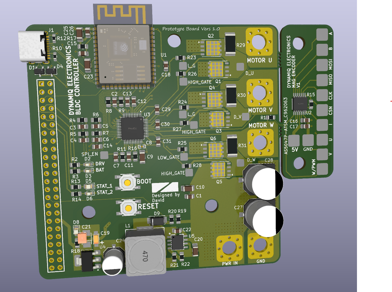 I'm currently on the journey of creating a simple cost effective controller that
will eventually be sold to the masses to remove the high barrier to entry into using high performing brushless motor actuators.
FRC Falcon 500 Motors inspired this project, since there are no suitable motor options at a suitable price that enables hobbyists to utilise these amazing pieces of technology. (Odrive being 200USD+)
(Do note this is actually my very second PCB designed, so I lack a lot of experience)
Version 1 of the PCB worked with the following code. However I ended up frying two of the boards during programming and tinkering with the board. I am currently working on a version 2 iteration of the PCB from the mistakes and lack of safety features in V1.
(I actually got the motor to turn on the very first iteration of this board which is a massive win)
The progress on the code is halted as I have no working boards anymore since I fried all 2 of them haha.
PCB was manufactured by JLPCB, assembly services was also opted, 5 boards were 10 bucks aud and assembly and parts for 2 board added $150 aud
Reddit also reviewd my board before I manufactured it heres the link to that discussion https://www.reddit.com/r/PCB/comments/1lk1n3d/review_request_my_first_pcb_bldc_sinusoidal/
This man made coding this thing a lot easier. Just pass sine waves into the motor and itll turn. I reckon it was much more easier to implement than step control. https://www.youtube.com/watch?v=zSdetJsSeNw&t
Cool channels
If you'd like to contact me for more information or collaboration on this project feel free to DM me on insta at DJAY10101, or if you prefer email its djay01602@gmail.com
| Qty | Value | Footprint | References |
|---|---|---|---|
| 12 | 10K | Resistor_SMD:R_0805_2012Metric_Pad1.20x1.40mm_HandSolder | R1, R4, R5, R6, R7, R8, R9, R11, R15, R17, R19, R21 |
| 9 | 0.1uF | Capacitor_SMD:C_0805_2012Metric_Pad1.18x1.45mm_HandSolder | C3, C4, C5, C6, C7, C15, C17, C18, C26 |
| 6 | 2.2 | Resistor_SMD:R_0805_2012Metric_Pad1.20x1.40mm_HandSolder | R23, R24, R25, R26, R27, R28 |
| 6 | N_FET_ISC0602NLS | Package_SON:Infineon_PG-TDSON-8_6.15x5.15mm | Q1, Q2, Q3, Q4, Q5, Q6 |
| 5 | 150 | Resistor_SMD:R_0805_2012Metric_Pad1.20x1.40mm_HandSolder | R2, R3, R13, R14, R18 |
| 3 | 100nF | Capacitor_SMD:C_0805_2012Metric_Pad1.18x1.45mm_HandSolder | C1, C2, C14 |
| 3 | 10mR | Resistor_SMD:R_2512_6332Metric_Pad1.40x3.35mm_HandSolder | R29, R30, R31 |
| 3 | 470nF 16V | Capacitor_SMD:C_0805_2012Metric_Pad1.18x1.45mm_HandSolder | C29, C30, C31 |
| 3 | HIGH_GATE | FootPrint_ESC:PAD_TP | TP22, TP23, TP24 |
| 2 | 100nF 50V | Capacitor_SMD:C_1206_3216Metric_Pad1.33x1.80mm_HandSolder | C9, C10 |
| 2 | 10uF | Capacitor_SMD:C_1206_3216Metric_Pad1.33x1.80mm_HandSolder | C20, C25 |
| 2 | 470uF -C3351 | easyeda2kicad:CAP-SMD_BD10.0-L10.3-W10.3-LS11.3-FD | C27, C28 |
| 2 | 5.1K | Resistor_SMD:R_0603_1608Metric_Pad0.98x0.95mm_HandSolder | R10, R12 |
| 2 | L_G | FootPrint_ESC:PAD_TP | TP19, TP20 |
| 2 | PSM712-LF-T7 | easyeda2kicad:SOT-23-3_L3.0-W1.7-P0.95-LS2.9-BR | D1, D4 |
| 2 | SW_MEC_5E | easyeda2kicad:SW-SMD_4P-L5.2-W5.2-P3.70-LS6.5 | SW1, SW2 |
| 1 | 0.01uF | Capacitor_SMD:C_0805_2012Metric_Pad1.18x1.45mm_HandSolder | C22 |
| 1 | 100nF 16V | easyeda2kicad:C0402 | C8 |
| 1 | 100uF | Capacitor_SMD:C_1206_3216Metric_Pad1.33x1.80mm_HandSolder | C23 |
| 1 | 10uF - TAJA106K016RNJ | easyeda2kicad:CAP-SMD_L3.2-W1.6-RD-C7171 | C19 |
| 1 | 15uH | easyeda2kicad:IND-SMD_L12.5-W12.5_RLF12545T | L1 |
| 1 | 1K | Resistor_SMD:R_0805_2012Metric_Pad1.20x1.40mm_HandSolder | R20 |
| 1 | 1uF | Capacitor_SMD:C_0805_2012Metric_Pad1.18x1.45mm_HandSolder | C16 |
| 1 | 2.2uF | Capacitor_SMD:C_0805_2012Metric_Pad1.18x1.45mm_HandSolder | C13 |
| 1 | 220uF-C3342 | easyeda2kicad:CAP-SMD_BD6.3-L6.6-W6.6-FD | C24 |
| 1 | 22nF 100V | Capacitor_SMD:C_0805_2012Metric_Pad1.18x1.45mm_HandSolder | C11 |
| 1 | 22uF Tant TAJB226K010RNJ | easyeda2kicad:CAP-SMD_L3.5-W2.8-R-RD | C21 |
| 1 | 3.3K | Resistor_SMD:R_0805_2012Metric_Pad1.20x1.40mm_HandSolder | R22 |
| 1 | 4.7uF | Capacitor_SMD:C_0805_2012Metric_Pad1.18x1.45mm_HandSolder | C12 |
| 1 | 47 | Resistor_SMD:R_0805_2012Metric_Pad1.20x1.40mm_HandSolder | R16 |
| 1 | 5V_ENCODER | FootPrint_ESC:Small_Pad_4mm | TP10 |
| 1 | AMS1117-3.3 | Package_TO_SOT_SMD:SOT-223-3_TabPin2 | U4 |
| 1 | AS5047P-ATSM_C962063 | easyeda2kicad:TSSOP-14_L5.0-W4.4-P0.65-LS6.4-BL | U2 |
| 1 | A_ENCODER | FootPrint_ESC:Small_Pad_4mm | TP8 |
| 1 | BAT_GND | FootPrint_ESC:PWR_THRU_HOLE | GND |
| 1 | BAT_IN | FootPrint_ESC:PWR_THRU_HOLE | PWR IN |
| 1 | B_ENCODER | FootPrint_ESC:Small_Pad_4mm | TP7 |
| 1 | CLK_ENCODER | FootPrint_ESC:Small_Pad_4mm | TP3 |
| 1 | CSN_ENCODER | FootPrint_ESC:Small_Pad_4mm | TP2 |
| 1 | D_U | FootPrint_ESC:PAD_TP | TP25 |
| 1 | D_V | FootPrint_ESC:PAD_TP | TP26 |
| 1 | D_W | FootPrint_ESC:PAD_TP | TP27 |
| 1 | ESP32-S3-WROOM-1 | PCM_Espressif:ESP32-S3-WROOM-1 | U1 |
| 1 | Fault_LED | LED_SMD:LED_0603_1608Metric_Pad1.05x0.95mm_HandSolder | D2 |
| 1 | GND_ENCODER | FootPrint_ESC:Small_Pad_4mm | TP6 |
| 1 | HC-PM254-8.5H-2X24PZ | easyeda2kicad:HDR-TH_48P-P2.54-V-F-R2-C24-S2.54 | H1 |
| 1 | I_ENCODER | FootPrint_ESC:Small_Pad_4mm | TP9 |
| 1 | LED | LED_SMD:LED_0805_2012Metric_Pad1.15x1.40mm_HandSolder | D8 |
| 1 | LIPO_ALERT | LED_SMD:LED_0603_1608Metric_Pad1.05x0.95mm_HandSolder | D3 |
| 1 | LOW_GATE | FootPrint_ESC:PAD_TP | TP21 |
| 1 | MISO_ENCODER | FootPrint_ESC:Small_Pad_4mm | TP4 |
| 1 | MOSI_ENCODER | FootPrint_ESC:Small_Pad_4mm | TP5 |
| 1 | Motor_Phase_U | FootPrint_ESC:PWR_THRU_HOLE | MOTOR U |
| 1 | Motor_Phase_V | FootPrint_ESC:PWR_THRU_HOLE | MOTOR V |
| 1 | Motor_Phase_W | FootPrint_ESC:PWR_THRU_HOLE | MOTOR W |
| 1 | SPI_EN | FootPrint_ESC:PAD_TP | TP1 |
| 1 | SS34 | easyeda2kicad:SMA_L4.3-W2.6-LS5.2-RD | D9 |
| 1 | STATUS_1_LED | LED_SMD:LED_0805_2012Metric_Pad1.15x1.40mm_HandSolder | D5 |
| 1 | STATUS_2_LED | LED_SMD:LED_0603_1608Metric_Pad1.05x0.95mm_HandSolder | D6 |
| 1 | TMC6200-TA-T | easyeda2kicad:TQFP-48_L7.0-W7.0-P0.50-LS9.0-BL-EP | U3 |
| 1 | TPS5430DDAR | easyeda2kicad:ESOP-8_L4.9-W3.9-P1.27-LS6.0-TL-EP | U5 |
| 1 | USB_C_Receptacle_USB2.0_16P | easyeda2kicad:USB-C_SMD-TYPE-C-31-M-12 | J1 |
| 1 | U_ENCODER | FootPrint_ESC:Small_Pad_4mm | TP11 |
| 1 | V_ENCODER | FootPrint_ESC:Small_Pad_4mm | TP12 |
| 1 | W/PWM_ENCODER | FootPrint_ESC:Small_Pad_4mm | TP13 |
The 113 most common of 118 parts.
DJAY101/Dynamiq_BLDC_Controller
Bringing brushless motor control to the masses

acanyulaf/24V-10A-BLDC-Driver
This is a technical assignment problem given by Kuartis. The aim is to design a 24V/10A BLDC controller. There will be also an I2C or SPI interface for control inputs.

TrendBit/SMBR-hardware
Design file for SMBR hardware modules in KiCAD.


cjheath/jlcbasic
JLC Basic parts library for Kicad fetched and converted from EasyEDA

Kilan777/HomeDeck
Jarvis HomeDeck: a Raspberry Pi CM4 carrier board and voice-assistant software for a 7-inch smart display (KiCad hardware, generated from Python, plus the Python/JS assistant)

xmyoot/esp32-media-carrier
ESP32 multimedia carrier board with 7–24 V DC buck regulator, 3.2 W Class-D I2S audio amp, WS2812 LED ring driver, and SPI TFT display header


igorilla666/water-controller
Scheda di controllo basata sul modulo Waveshare ESP32-S3-ETH, con ingressi sensore, RS-485, pilotaggio rele, buzzer e alimentazione/protezioni dedicate.
It measures 98.8 × 80 mm and has 4 copper layers, 1.6 mm thick.
118 parts, built around the ESP32-S3-WROOM-1-N8, TMC6200-TA-T, TPS5430DDAR and AMS1117-3.3. The full list of its parts is on this page, with links to each part's symbol and footprint where PCBKit's library has them.
From the DJAY101/Dynamiq_BLDC_Controller repository on GitHub, at the commit this page was made from: the board is PCB_FILES_Version1/Brushless_Controller_Test_Board.kicad_pcb and its schematic PCB_FILES_Version1/Brushless_Controller_Test_Board.kicad_sch. PCBKit opens the board in the browser, with nothing to install.
Its repository publishes it under the GPL-3.0 licence: you may reuse it on that licence's terms (keep the author's notice, and for a copyleft licence share your changes alike).