2 layers60 × 70 mm
Media controller
bgb-0/media-controller
Open-source USB-C media controller. RP2040, 3× MX hot-swap keys, EC11 encoder, SSD1306 OLED. KiCad + QMK.
42 parts1GPL-2.0

 dj505/Clipboard3
A macropad for copy/pasting, and more!
Clippy is an open-source printed circuit board by dj505, from the dj505/Clipboard repository on GitHub. It is a 2-layer board of 61.2 × 38.4 mm with 19 parts on 26 nets, routed with 161 tracks and 10 vias.
It is built around the SN74LV1T34DBV, SK6812MINI-E and PEC12R-4215F-S0024. Its parts include 7 diodes, 3 capacitors, 2 ICs, 1 connector and 1 switch. It belongs with the keyboards and input boards of this library.


A macropad made to make copy/paste easier
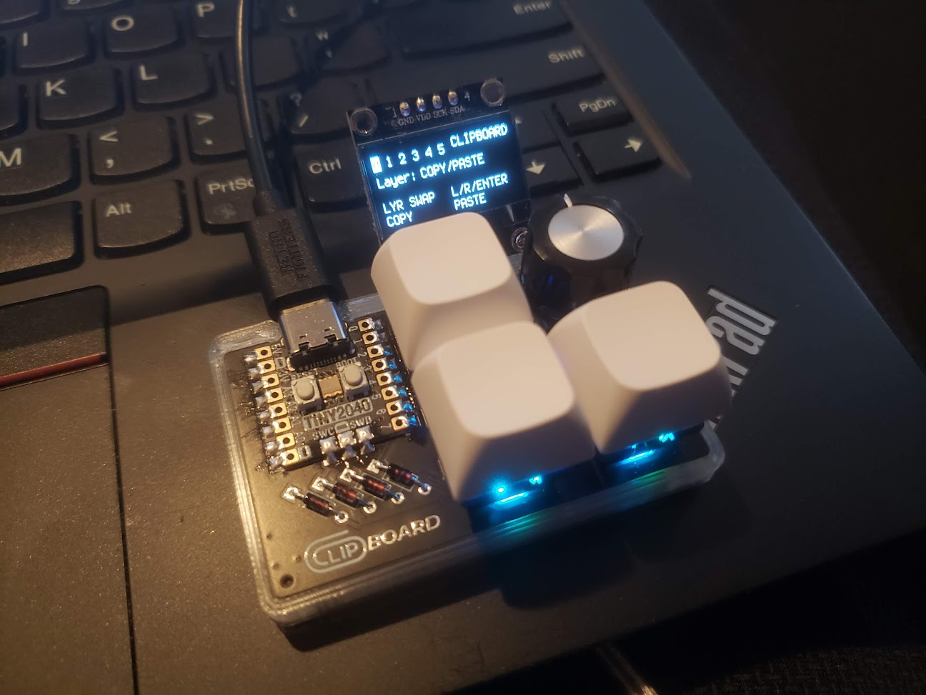
Yes! There's no reason you have to use this exclusively for copy/pasting, or other common shortcuts. You can do whatever you want with it, really. I was comissioned to design this by a friend who does a lot of copy/pasting at work. As he would like to save himself from a perpetually sore wrist, it was designed to the specifications he provided, right down to the specific intended use case. Since it's meant to be used for copying and pasting in an office-like environment, "Clipboard" just so happened to be a good play on words. (Shoutouts to clue for pointing that out!)
Short answer: Because I already have the parts lol
Long answer: To keep costs down, the deisgn was made to use parts we (myself and the friend who commissioned this board) already own. We both have a spare Tiny2040, I have hundreds of 1N4148 diodes from making keyboards, and I also have tons of leftover Kailh sockets and SK6812MINI-Es from the initial run of the PicoLX.
The RP2040 Zero is significantly cheaper and has a near-identical pinout. Some pins remain unused but you can solder straight to the pins if you want to add any extra peripherals.
| Part | Package | Qty |
|---|---|---|
| 100nF Capacitor | 0805 | 3 |
| 1N4148 Diode | DO-35 | 4 |
| SK6812MINI-E | MINI-E | 3 |
| Keyboard Switch | MX-style | 3 |
| Rotary Encoder | PEC12R-4215F-S0024 | 1 |
| Pimoroni Tiny2040 | N/A | 1 |
| SN74LV1T34DBV | SOT-23-5 | 1 |
This board was developed using KMK Firmware. Instructions for setting up KMK on your board can be found in the Getting Started docs.
After KMK itself is set up, delete the existing code.py or main.py on the CIRCUITPY drive, and copy the code.py file in this repository's "keymap" directory to the root of the drive.
You're done!
CircuitPython libraries can be found here.
This project will require the following libraries from the "lib" folder of the library bundle:
Clipboard is made with an I2C 128x64 SSD1306 OLED display in mind. If you have a different display with a different resolution, you will have to edit code.py accordingly. The underside of the board has the appropriate pins marked, with SDA on GP26 and SCL on GP27. The VCC (or VDD (or 3.3V)) pin on the OLED should be wired to the +3V3 pin on the Clipboard.
rp2040 directory. The following changes were made to the pcbnew footprint for this project:
| Qty | Value | Footprint | References |
|---|---|---|---|
| 4 | 1N4148 | Diode_THT:D_DO-35_SOD27_P7.62mm_Horizontal | D1, D2, D3, D4 |
| 3 | 100nF | Capacitor_SMD:C_0805_2012Metric_Pad1.18x1.45mm_HandSolder | C1, C2, C3 |
| 3 | MX-NoLED | MX_Hotswap:MX-Hotswap-1U | MX1, MX2, MX3 |
| 3 | SK6812MINI-E | marbastlib-mx:LED_MX_6028R | LED1, LED2, LED3 |
| 1 | Conn_01x08 | Connector_PinHeader_2.54mm:PinHeader_1x08_P2.54mm_Vertical | J1 |
| 1 | PEC12R-4215F-S0024 | Rotary_Encoder:RotaryEncoder_Bourns_Vertical_PEC12R-3xxxF-Sxxxx | SW1 |
| 1 | SN74LV1T34DBV | Package_TO_SOT_SMD:SOT-23-5 | U2 |
| 1 | tiny2040 | tiny2040:tiny2040 | U1 |
The 17 most common of 19 parts.
It measures 61.2 × 38.4 mm and has 2 copper layers, 1.6 mm thick.
19 parts, built around the SN74LV1T34DBV, SK6812MINI-E and PEC12R-4215F-S0024. The full list of its parts is on this page, with links to each part's symbol and footprint where PCBKit's library has them.
From the dj505/Clipboard repository on GitHub, at the commit this page was made from: the board is Clippy.kicad_pcb and its schematic Clippy.kicad_sch. PCBKit opens the board in the browser, with nothing to install.
Its repository states no licence, so its author keeps all rights: ask dj505 before reusing the design.
bgb-0/media-controller
Open-source USB-C media controller. RP2040, 3× MX hot-swap keys, EC11 encoder, SSD1306 OLED. KiCad + QMK.


TweetyDaBird/Fat-Chameleon
A Grid Ortho keyboard for BM40, JJ40/JJ50 cases inspired by Planck and Preonic


TweetyDaBird/Skinny-Chameleon
The Skinny Chameleon is a grid type orthogonal keyboard made to be a direct drop-in for the Preonic's and Planck's PCB's.

SbRhubarbPie/PieBoard
A full sized custom keyboard made as a project for Hack Club's Highway to Undercity


holeminhnhat3101/Cosmos-docks
Cosmos-docks is a custom hackpad created by me. It includes a custom PCB, a fully 3D-printable case, one rotary encoder, an OLED display, and SK6812MINI-E addressable RGB LEDs.