4 layers74.5 × 69.2 mm
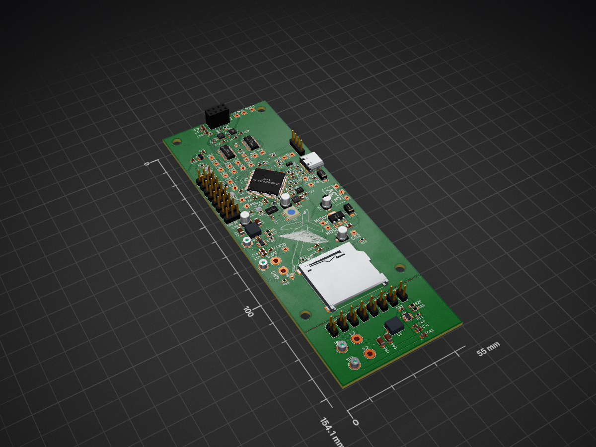
 Dizzerin/Rocket-Flight-Data-Computer1
This project uses an STM32H743VGT6 MCU along with some innertial measurement units (IMU)s and barometric pressure sensors to and an SD card to record flight data from a model rocket and for later analysis, graphing, and plotting using Python.
GPS module is an open-source printed circuit board by Dizzerin, from the Dizzerin/Rocket-Flight-Data-Computer repository on GitHub. It is a 4-layer board of 55 × 154.1 mm with 161 parts on 173 nets, routed with 1,266 tracks and 325 vias.
It is built around the BME680, MMC5983MA and MS5611-01BA03, with the SN74LVC8T245PW, AMS1117-3.3 and ICM-20948 among its other parts. Its parts include 45 capacitors, 29 resistors, 20 connectors, 12 ICs and 5 diodes. It belongs with the sensors and measurement and radio and wireless boards and the STM32 boards of this library.


A flight data logger for model rockets built around the STM32H743VGT6 microcontroller. It records inertial (accelerometer + gyroscope) data at 100Hz and environmental (pressure, temperature, humidity) data at 20Hz to an SD card in CSV format for post-flight analysis, graphing, and plotting.
Known Limitations and Bugs
Future Improvements
MCU: STM32H743VGT6 — ARM Cortex-M7, running at 64 MHz (internal HSI oscillator, no PLL)
| Peripheral | Interface | User Module | Description |
|---|---|---|---|
| LSM6DSO32 IMU | SPI1 (16-bit) | Middlewares/ST/lsm6dso/lsm6dso32_device.c/.h | 6-axis IMU — accelerometer up to ±32 g (scale configurable via LSM6DSO_ACCEL_FS), gyroscope up to ±2000 dps (scale configurable via LSM6DSO_GYRO_FS), 104 Hz ODR — see lsm6dso32_device.h |
| BME680 Barometer | SPI3 (8-bit) | UserCode/bme680_device.c/.h | Pressure, temperature, humidity — forced-mode, 20 Hz triggered |
| SD Card | SPI2 (8-bit) | UserCode/SD_Card.c/.h | FAT filesystem via FatFs — CSV data logging |
| LED | GPIO (PB3) | Core/Src/main.c | Heartbeat blink (1 Hz); fast-blink on fatal error |
The accelerometer and gyroscope full-scale ranges are set by two #defines at the top of lsm6dso32_device.h. Change only the #define — the correct conversion function is selected automatically at init time.
| Define | Default | Options |
|---|---|---|
LSM6DSO_ACCEL_FS | LSM6DSO32_16g | LSM6DSO32_4g / _8g / _16g / _32g |
LSM6DSO_GYRO_FS | LSM6DSO32_2000dps | LSM6DSO32_125dps / _250dps / _500dps / _1000dps / _2000dps |
If the BME680 is in a sealed or partially-sealed enclosure on the rocket, ram air pressure at high velocity can add a stagnation pressure on top of the static pressure, making the sensor read higher than true static pressure and therefore lower than true altitude. For a rocket traveling at 100 m/s (360 km/h), the dynamic pressure is:
q = 0.5 × ρ × v² = 0.5 × 1.225 × 100² ≈ 6125 Pa = 61 hPa
This would cause a significant altitude error. To avoid this, the sensor enclosure should be vented with a small port facing perpendicular to the airflow (not forward-facing), so it sees only static pressure.
Rocket-Flight-Data-Computer/
├── STM32_CubeIDE_Rocket_Project/       # STM32CubeIDE firmware project
│   ├── Core/
│   │   ├── Inc/main.h                  # CubeMX-generated pin/peripheral definitions
│   │   └── Src/main.c                  # Startup, init, scheduler registration
│   ├── UserCode/                       # User-written application code
│   │   ├── DataLogger.c/.h             # Ties IMU + BME680 → SD card CSV rows
│   │   ├── Scheduler.c/.h              # Cooperative task scheduler
│   │   ├── SD_Card.c/.h                # SD card state machine + FatFs wrappers
│   │   └── bme680_device.c/.h          # BME680 wrapper around Bosch API
│   ├── Middlewares/
│   │   ├── Third_Party/BOSCH_BME/      # Bosch BME68x SensorAPI v4.4.8
│   │   │   ├── bme68x.c
│   │   │   ├── bme68x.h
│   │   │   └── bme68x_defs.h
│   │   ├── Third_Party/FatFs/          # Chan's FatFs (bundled via STM32CubeMX)
│   │   └── ST/lsm6dso/                 # ST LSM6DSO32 register-level driver
│   │       ├── lsm6dso32_device.c/.h   # High-level init/read functions
│   │       └── lsm6dso32_reg.c/.h      # Low-level register map (ST-provided)
│   └── Drivers/                        # STM32 HAL (CubeMX-generated)
├── PCB_Schematics_KiCAD/               # KiCad PCB schematic files
├── Python_Data_Analyzer/               # Post-flight data analysis scripts
├── Datasheets/                         # Component datasheets
└── README.md
CubeMX note: Files in
Core/are managed by STM32CubeMX. All user edits inside those files must stay within/* USER CODE BEGIN *///* USER CODE END */blocks to survive code regeneration.
| Library | Version | Location in Repo | Source |
|---|---|---|---|
| Bosch BME68x SensorAPI | v4.4.8 | Middlewares/Third_Party/BOSCH_BME/ | github.com/boschsensortec/BME68x_SensorAPI |
| ST LSM6DSO32 driver | (STM32CubeH7) | Middlewares/ST/lsm6dso/ | github.com/STMicroelectronics/lsm6dso32-pid |
| FatFs | R0.12c | Middlewares/Third_Party/FatFs/ | Bundled by STM32CubeMX (Chan's FatFs) |
| STM32 HAL / BSP | STM32CubeH7 | Drivers/ | Bundled by STM32CubeMX |
The Bosch BME68x SensorAPI and ST LSM6DSO32 driver files are not modified. Custom wrappers (
bme680_device.c/.handlsm6dso32_device.c/.h) sit on top of them.
The firmware uses a non-blocking cooperative scheduler. There is no RTOS — all modules are polled from a single main loop via Scheduler_Run(). No HAL_Delay() calls exist in the main loop or in any task function.
main.c  (init + main loop)
  └── Scheduler_Run()
        │
        ├── DataLogger_StateMachine_Task  [every 5 ms]
        │     │
        │     ├── bme680_device           (BME680 wrapper)
        │     │     └── Bosch BME68x API  (bme68x.c)
        │     │
        │     ├── lsm6dso32_device        (IMU high-level driver)
        │     │     └── lsm6dso32_reg     (ST register-level driver)
        │     │
        │     └── SD_Card                 (file write wrappers)
        │           └── FatFs             (ff.c)
        │
        ├── SD_StateMachine               [every 100 ms]
        │     └── SD_Card (mount/detect state machine)
        │
└── LED_Toggle [every 500 ms]Pin: PB3 (LED_Pin, LED_GPIO_Port) — active-high. Note: PB3 is a test pad only in the current PCB schematic and is not connected to a discrete LED component.
The LED flash pattern indicates current system state at a glance:
| State | Pattern | Period | Rate |
|---|---|---|---|
| Running — not logging (no SD card or SD not yet mounted) | 500 ms on, 250 ms off | 750 ms | ~1.3 Hz |
| Running — actively logging to SD card | 250 ms on, 250 ms off | 500 ms | 2 Hz |
Fatal error (Error_Handler()) | 100 ms on, 100 ms off | 200 ms | 5 Hz |
| Locked up, infinite loop, unpowered | Stuck on or stuck off | — | — |
The LED task (LED_Task in main.c) is registered with the scheduler at a 50 ms poll interval and manages its own asymmetric on/off timing internally using HAL_GetTick(). It queries DataLogger_IsLogging() each cycle to select the correct flash pattern. The Error_Handler() fast-blink runs as a busy-wait loop after interrupts are disabled, so it does not depend on the scheduler or SysTick.
Files: UserCode/Scheduler.c / Scheduler.h
A lightweight cooperative task scheduler based on HAL_GetTick() (1 ms SysTick resolution). Each task is a void fn(void) function pointer with an associated period in milliseconds.
Scheduler_Init() — resets the task list at startup.Scheduler_RegisterTask(fn, periodMs) — registers a task; records HAL_GetTick() as the initial baseline so the first execution is deferred by one full period.Scheduler_Run() — called in the while(1) main loop. Iterates all registered tasks; executes any whose elapsed time (HAL_GetTick() - lastRunTick) has reached or exceeded their period.All elapsed-time comparisons use unsigned 32-bit subtraction, which is inherently wrap-around safe across the full 49.7-day HAL_GetTick() rollover range — the same pattern used throughout the codebase.
SCHEDULER_MAX_TASKS)| Task Function | Period | Effective Rate | Description |
|---|---|---|---|
DataLogger_StateMachine_Task | 5 ms | 200 Hz | Polls BME680 state machine; reads IMU and writes CSV at 100 Hz sub-interval |
SD_StateMachine | 100 ms | 10 Hz | Processes SD card insert/remove events, manages mount state |
LED_Toggle | 500 ms | 2 Hz (1 Hz blink) | Heartbeat LED on PB3 |
Files: UserCode/DataLogger.c / DataLogger.h
The DataLogger is the central orchestrator. It reads from both sensors and writes a row to the CSV log file on every IMU read cycle.
| Interval Constant | Value | Action |
|---|---|---|
| Task schedule period | 5 ms | DataLogger_StateMachine_Task is called by the scheduler |
DATALOGGER_BME_TRIGGER_MS | 50 ms (20 Hz) | Triggers a new BME680 forced-mode measurement |
DATALOGGER_CSV_WRITE_MS | 10 ms (100 Hz) | Reads IMU + writes one CSV row |
DATALOGGER_SYNC_MS | 1000 ms (1 Hz) | Calls f_sync to flush data to physical SD card media |
bme680_stateMachine() is polled. If the BME680 has completed a measurement, the result is cached in bmeCache.bme680_triggerMeasurement() starts a new forced-mode TPHG conversion.lsm6_readData() reads fresh IMU data (accel, gyro, temperature), then writeCSVRow() writes one row to the open log file using the latest IMU data and the most recently cached BME680 data.SD_FileSync() flushes the file to physical media. Worst-case data loss on sudden power loss is 1 second of data.DL_IDLE ──(SD mounts)──► DL_OPENING ──(file created)──► DL_LOGGING
▲ │
└────────────────(SD card removed)─────────────────────────┘
│
(f_write error)
▼
DL_ERROR| State | Description |
|---|---|
DL_IDLE | Sensors polled, but SD card not mounted or no file open |
DL_OPENING | SD just mounted; scanning for next available log filename |
DL_LOGGING | File open and active; writing CSV rows every 10 ms |
DL_ERROR | File operation failed; waits for card removal and re-insertion |
Before the BME680 completes its first measurement, the four BME columns in the CSV are written as empty fields (consecutive commas). Normal data appears from the second or third row onward.
Files: UserCode/SD_Card.c / SD_Card.h
Provides a thin state-machine wrapper around FatFs for safer hot-plug card handling and simple file I/O.
SD_CARD_DETECT (PA8), active-low, hardware pull-up on the PCBSD_StateMachine() processes the event flag and reads the current pin level to distinguish insertion from removalSD_NOT_PRESENT ──(card inserted)──► SD_PRESENT_UNMOUNTED
│ (500 ms settle)
▼
SD_MOUNTING
/ \
(f_mount OK) (f_mount fail)
│ │
▼ ▼
SD_MOUNTED SD_ERROR
│
(card removed from any state)
│
▼
SD_NOT_PRESENT| State | Description |
|---|---|
SD_NOT_PRESENT | No card detected |
SD_PRESENT_UNMOUNTED | Card inserted; waiting 500 ms for power/signal settling |
SD_MOUNTING | f_mount() in progress |
SD_MOUNTED | Filesystem mounted; file operations available |
SD_ERROR | Mount failed; waits for card removal before retrying |
Log files are named LOG_XXXX.CSV in 8.3 FAT format (LFN disabled):
LOG_0001.CSV through LOG_9999.CSVLOG_0003.CSV exists, creates LOG_0004.CSV)LOG_9999.CSV is overwrittenAll functions return FR_NOT_READY if the card is not in SD_MOUNTED state.
| Function | Description |
|---|---|
SD_FileOpen(fp, path, mode) | Open or create a file |
SD_FileClose(fp) | Close a file |
SD_FileWrite(fp, buf, len, bw) | Write data |
SD_FileSync(fp) | Flush data sector, FAT, and directory entry to physical media |
SD_DirOpen / SD_DirRead / SD_DirClose | Directory traversal (used for log number scan) |
SD_GetState() | Returns current SD_State_t |
Each power-on or SD card insertion creates a new LOG_XXXX.CSV file. The first line is the CSV header; subsequent lines are data rows written at 100 Hz (one row every 10 ms).
WriteTime_ms,IMU_Timestamp_ms,Accel_New,Accel_X_mg,Accel_Y_mg,Accel_Z_mg,Gyro_New,Gyro_X_mdps,Gyro_Y_mdps,Gyro_Z_mdps,Temp_New,IMU_Temp_C,BME_Timestamp_ms,Pressure_hPa,BME_Temp_C,Humidity_pctRH,Altitude_AGL_ft| # | Column Name | Unit | Format | Min | Max | Typical at Rest / Notes |
|---|---|---|---|---|---|---|
| 1 | WriteTime_ms | ms | %lu | 0 | 4,294,967,295 | Wall-clock tick at time of row write (rolls over after ~49.7 days) |
| 2 | IMU_Timestamp_ms | ms | %lu | 0 | 4,294,967,295 | HAL_GetTick() captured at SPI read time |
| 3 | Accel_New | flag | %u | 0 | 1 | 1 = fresh accelerometer data this row; 0 = repeated from previous read |
| 4 | Accel_X_mg | milli-g | %.2f | −32000 | +32000 | ~0 mg at rest (sensor X-axis horizontal); actual range depends on LSM6DSO_ACCEL_FS |
| 5 | Accel_Y_mg | milli-g | %.2f | −32000 | +32000 | ~0 mg at rest (sensor Y-axis horizontal); actual range depends on LSM6DSO_ACCEL_FS |
| 6 | Accel_Z_mg | milli-g | %.2f | −32000 | +32000 | ~+1000 mg at rest (1 g gravity on Z-axis); actual range depends on LSM6DSO_ACCEL_FS |
| 7 | Gyro_New | flag | %u | 0 | 1 | 1 = fresh gyroscope data this row |
| 8 | Gyro_X_mdps | milli-dps | %.2f | −2,000,000 | +2,000,000 | ~0 mdps at rest; actual range depends on LSM6DSO_GRYO_FS |
| 9 | Gyro_Y_mdps | milli-dps | %.2f | −2,000,000 | +2,000,000 | ~0 mdps at rest; actual range depends on LSM6DSO_GRYO_FS |
| 10 | Gyro_Z_mdps | milli-dps | %.2f | −2,000,000 | +2,000,000 | ~0 mdps at rest; actual range depends on LSM6DSO_GRYO_FS |
| 11 | Temp_New | flag | %u | 0 | 1 | 1 = fresh IMU die temperature this row |
| 12 | IMU_Temp_C | °C | %.2f | −40 | +85 | ~25 °C at room temperature |
| 13 | BME_Timestamp_ms | ms | %lu | 0 | 4,294,967,295 | HAL_GetTick() when BME680 measurement completed; empty until first reading |
| 14 | Pressure_hPa | hPa | %.2f | 300 | 1100 | ~1013 hPa at sea level; ~950 hPa at 500 m altitude; empty until first reading |
| 15 | BME_Temp_C | °C | %.2f | −40 | +85 | ~20–30 °C indoors; empty until first reading |
| 16 | Humidity_pctRH | %RH | %.2f | 0 | 100 | ~30–60 %RH indoors; empty until first reading |
| 17 | Altitude_AGL_ft | ft | %.2f | — | — | AGL altitude from barometric formula; reads 0.00 during the ground pressure calibration window; altitude computation begins once GROUND_PRESSURE_NUM_SAMPLES BME680 readings have been averaged into P₀; empty until first BME reading |
Notes:
Accel_New, Gyro_New, and Temp_New flags indicate whether the LSM6DSO's data-ready status register reported fresh data at the time of that specific SPI read. Even when 0, the value columns contain the most recent valid reading.WriteTime_ms and IMU_Timestamp_ms could differ by 1–2 ms due to SPI read overhead.Altitude_AGL_ft is computed on-board using h = 44330 × (1 − (P/P₀)^0.1903) × 3.28084. P₀ is the average of the first GROUND_PRESSURE_NUM_SAMPLES valid BME680 pressure readings after power-on or SD card insertion.12345,12344,1,23.50,-15.25,998.00,1,120.30,-45.10,30.20,1,27.43,12300,1013.25,24.61,52.30,125.48For even more details on this log file, see the Flight Data Reference document.
Debug messages are sent over UART3 at 115200 baud, 8N1 using the myprintf() function (works like printf, outputs to UART3). This is useful for verifying sensor initialization and logging state transitions.
Important: The PCB runs at 3.3 V logic levels. Use a bridge that supports 3.3 V (or is 3.3 V tolerant). Do not use a 5 V TTL bridge without a level shifter.
| PCB Pin | PCB Signal | Connect To |
|---|---|---|
| PB10 | UART3 TX (PCB transmits here) | RX on USB bridge |
| PB11 | UART3 RX (PCB receives here) | TX on USB bridge |
| GND | Ground | GND on USB bridge |
| 3.3 V | Power reference | 3.3 V (VCC) on USB bridge |
TX and RX are always crossed: the PCB's TX connects to the bridge's RX, and the PCB's RX connects to the bridge's TX.
On the host PC, open the bridge's COM/tty port at 115200 baud, 8 data bits, no parity, 1 stop bit using any serial terminal (e.g., PuTTY, RealTerm, Tera Term, screen, minicom).
To see CSV rows printed live to the debug UART during bench testing, set DATALOGGER_UART_ECHO to 1 in DataLogger.h:
#define DATALOGGER_UART_ECHO     1    /* 0 = disabled (default), 1 = enabled */
#define DATALOGGER_UART_ECHO_MS  500U /* print interval in ms (default 2 Hz) */
Why the rate limit? myprintf() is blocking — a worst-case 147-byte row takes ~12.8 ms to transmit at 115200 baud, which is longer than the 10 ms CSV write period. Printing at 100 Hz would also require ~14,700 bytes/sec, exceeding the UART's ~11,520 byte/sec capacity. At the default 500 ms interval, UART load is ~294 bytes/sec and the brief blocking window (~12.8 ms every 500 ms) has negligible impact on logging. Set DATALOGGER_UART_ECHO back to 0 before flight — the debug printing code is disabled by default and doesn't even compile when 0.
On a successful boot you should see messages similar to:
LSM6DSO init OK
BME680 init OK (chip ID 0x61)
DataLogger init OK
SD card not present
When a card is inserted:
SD card inserted — mounting...
SD mounted OK
DataLogger: opened LOG_0005.CSV| Peripheral | SPI Handle | Data Size | Clock Speed | Mode |
|---|---|---|---|---|
| LSM6DSO32 IMU | hspi1 | 8-bit | ~4 MHz (64 MHz / 16) | Mode 0 (CPOL=Low, CPHA=1Edge) |
| SD Card | hspi2 | 8-bit | ~250 kHz at init (64 MHz/256) → ~4 MHz at runtime (64 MHz/16) | Mode 0 (CPOL=Low, CPHA=1Edge) |
| BME680 | hspi3 | 8-bit | ~4 MHz (64 MHz / 16) | Mode 0 (CPOL=Low, CPHA=1Edge) |
| Signal | CubeMX Name | GPIO | Pin | Active |
|---|---|---|---|---|
| LSM6DSO32 chip select | LSM6DSO_CS_Pin | GPIOA | PA3 | Low |
| SD card chip select | SD_CS_Pin | GPIOB | PB12 | Low |
| BME680 chip select | BARO2_CS_Pin | GPIOC | PC9 | Low |
| SD card detect | SD_CARD_DETECT_Pin | GPIOA | PA8 | Low (card present) |
| LED | LED_Pin | GPIOB | PB3 | High |
All CS pins are configured as push-pull GPIO outputs. CS lines are driven by user code (not by the SPI peripheral hardware NSS). The SD card detect pin uses a hardware pull-up on the PCB and is connected to an EXTI line for interrupt-driven hot-plug detection.
| PCB Pin | PCB Signal | Connect To |
|---|---|---|
| PB10 | UART3 TX (PCB transmits here) | RX on USB bridge |
| PB11 | UART3 RX (PCB receives here) | TX on USB bridge |
| GND | Ground | GND on USB bridge |
| 3.3 V | Power reference | 3.3 V (VCC) on USB bridge |
| Qty | Value | Footprint | References |
|---|---|---|---|
| 30 | TestPoint | TestPoint:TestPoint_THTPad_2.0x2.0mm_Drill1.0mm | 3.1, 3.2, 3.3, 3.5, 3.31, 3.32, 3.34, MISO3, MOSI3, PB3, PB4, PB5, PB6, PB7, PB10, PB11 +14 |
| 17 | 100 nF | Capacitor_SMD:C_0603_1608Metric | C3, C4, C5, C6, C7, C17, C20, C24, C26, C27, C28, C29, C30, C36, C40, C43 +1 |
| 14 | 10 kohm | Resistor_SMD:R_0603_1608Metric | R3, R5, R8, R9, R11, R12, R19, R22, R23, R24, R25, R26, R27, R28 |
| 8 | Conn_01x02 | Connector_PinHeader_2.54mm:PinHeader_1x02_P2.54mm_Vertical | J13, J14, J15, J16, J17, J18, J19, J20 |
| 8 | Conn_01x03 | Connector_PinHeader_2.54mm:PinHeader_1x03_P2.54mm_Vertical | J4, J5, J6, J7, J8, J9, J10, J11 |
| 7 | 10 uF | Capacitor_SMD:C_0805_2012Metric | C15, C16, C21, C33, C34, C41, C42 |
| 6 | SolderJumper_2_Open | Jumper:SolderJumper-2_P1.3mm_Open_RoundedPad1.0x1.5mm | JP1, JP2, JP3, JP4, JP5, JP6 |
| 5 | 1 uF | Capacitor_SMD:C_0603_1608Metric | C9, C10, C11, C25, C32 |
| 5 | 22 ohm | Resistor_SMD:R_0603_1608Metric | R13, R14, R16, R17, R18 |
| 4 | 0.1 uF | Capacitor_SMD:C_0603_1608Metric | C12, C13, C14, C23 |
| 4 | 22 uF | Capacitor_SMD:C_1206_3216Metric | C18, C19, C44, C45 |
| 4 | TestPoint | TestPoint:TestPoint_Pad_D4.0mm | TP3, TP4, TP6, TP7 |
| 4 | TestPoint | TestPoint:TestPoint_THTPad_D4.0mm_Drill2.0mm | 5.0, 5.1, 5.2, 5.3 |
| 3 | 10 uF | Capacitor_SMD:C_Elec_4x5.4 | C31, C37, C39 |
| 3 | 100 kohm | Resistor_SMD:R_0805_2012Metric | R1, R4, R20 |
| 2 | 0 ohm | Resistor_SMD:R_0603_1608Metric | R10, R15 |
| 2 | 18 kohm | Resistor_SMD:R_0805_2012Metric | R2, R21 |
| 2 | 2.2 uF | Capacitor_SMD:C_0603_1608Metric | C1, C2 |
| 2 | 2.2 uH | Inductor_SMD:L_Bourns_SRP5030T | L1, L2 |
| 2 | 5.1 kohm | Resistor_SMD:R_0603_1608Metric | R6, R7 |
| 2 | SN74LVC8T245 | Package_SO:SSOP-24_3.9x8.7mm_P0.635mm | U10, U11 |
| 2 | SS34 | Diode_SMD:D_SMA | D2, D6 |
| 2 | TPS565208DDCR | TPS565208DDCR:SOT95P280X110-6N | U4, U12 |
| 1 | 1 Mohm | Resistor_SMD:R_0603_1608Metric | R29 |
| 1 | 22 uF | Capacitor_SMD:CP_Elec_4x5.3 | C22 |
| 1 | 4.7 nF | Capacitor_SMD:C_0603_1608Metric | C38 |
| 1 | 4.7 uF | Capacitor_SMD:C_0805_2012Metric | C35 |
| 1 | 600Ω@100MHz | Inductor_SMD:L_0603_1608Metric | FB1 |
| 1 | AMS1117-3.3 | Package_TO_SOT_SMD:SOT-223-3_TabPin2 | U6 |
| 1 | BME680 | Package_LGA:Bosch_LGA-8_3x3mm_P0.8mm_ClockwisePinNumbering | U8 |
| 1 | Buzzer | Buzzer_Beeper:Buzzer_12x9.5RM7.6 | BZ1 |
| 1 | Conn_01x04 | Connector_PinHeader_2.54mm:PinHeader_1x04_P2.54mm_Vertical | J3 |
| 1 | Conn_02x04_Odd_Even | Connector_PinSocket_2.54mm:PinSocket_2x04_P2.54mm_Vertical | J12 |
| 1 | ICM-20948 | Sensor_Motion:InvenSense_QFN-24_3x3mm_P0.4mm | U2 |
| 1 | LED | LED_SMD:LED_0805_2012Metric | D5 |
| 1 | LED_BGKR | LED_SMD:LED_SK6812_PLCC4_5.0x5.0mm_P3.2mm | D1 |
| 1 | LSM6DSO | Package_LGA:LGA-14_3x2.5mm_P0.5mm_LayoutBorder3x4y | U7 |
| 1 | MMC5983MA | MMC5983MA:PQFN50P300X300X100-16N | U9 |
| 1 | MS5611-01BA | Package_LGA:LGA-8_3x5mm_P1.25mm | U3 |
| 1 | MountingHole | Logo1:idk1 | H1 |
| 1 | SD_Card_Receptacle | Connector_Card:SD_TE_2041021 | J1 |
| 1 | SP0502BAHT | Package_TO_SOT_SMD:SOT-23 | D3 |
| 1 | STM32H743VGTx | Package_QFP:LQFP-100_14x14mm_P0.5mm | U1 |
| 1 | TLV70018_SOT23-5 | Package_TO_SOT_SMD:SOT-23-5 | U5 |
| 1 | TestPoint | TestPoint:TestPoint_Pad_D2.0mm | TP5 |
| 1 | USB_C_Receptacle_USB2.0_16P | Connector_USB:USB_C_Receptacle_GCT_USB4105-xx-A_16P_TopMnt_Horizontal | J2 |
It measures 55 × 154.1 mm and has 4 copper layers, 1.6 mm thick.
161 parts, built around the BME680, MMC5983MA, MS5611-01BA03 and SN74LVC8T245PW. The full list of its parts is on this page, with links to each part's symbol and footprint where PCBKit's library has them.
From the Dizzerin/Rocket-Flight-Data-Computer repository on GitHub, at the commit this page was made from: the board is PCB_Schematics_KiCAD/GPS module.kicad_pcb and its schematic PCB_Schematics_KiCAD/GPS module.kicad_sch. PCBKit opens the board in the browser, with nothing to install.
Its repository states no licence, so its author keeps all rights: ask Dizzerin before reusing the design.


jrtaylor71/Smart-Thermostat-Alt-Firmware
A comprehensive, feature-rich smart thermostat firmware for ESP32-S3 microcontrollers with touch display, web interface, and Home Assistant integration.

ajisrawi/DroneMagNav2.0
DroneMagNav 2.0 - survey-fluxgate magnetic-anomaly navigation board for drones (IGRF-14 + EMAG2v3 continued to flight altitude)


Conor-Dunlop/FYP_datalogger
render of the datalogger with power board (yes i know it need routed)


yagamy4680/drone-study
AUAV-OpenSource/FMUv4-PixRacer is the open hardware design of PixHawk FMUv4. It uses STM32F427 and MPU6000. (github)