
4 layers37 × 64.5 mm
IEMU Sensor Core
ponderononon/IEMU_DevBoards
Kicad Schematic Files for the BASE and SENSOR Development Boards (Layout in Progress)
27 parts
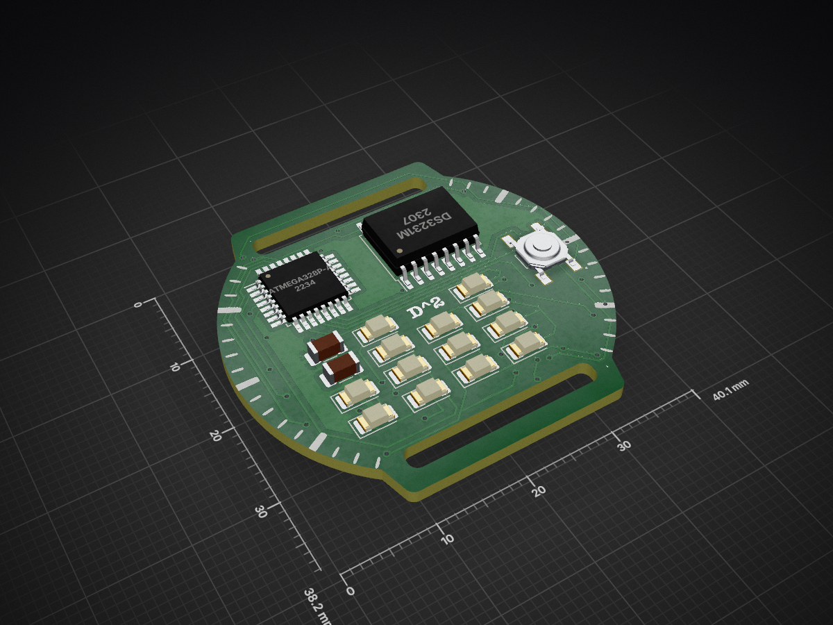
PCB designs and firmware for a wearable watch that displays 24 hr time in binary
Watch is an open-source printed circuit board by dividurga, from the dividurga/BinaryWatch repository on GitHub. It is a 2-layer board of 40.1 × 38.2 mm with 27 parts on 35 nets, routed with 354 tracks and 52 vias.
It is built around the ATMEGA328P-AU, DS3231MZ+ and HU2032-LF. Its parts include 13 diodes, 7 resistors, 3 ICs, 2 capacitors and 1 connector. It belongs with the wearables boards and the AVR (ATmega, ATtiny) boards of this library.


Welcome to the Binary Watch project! This repository contains all the files related to the design and development of binary watches using STM32 and ATMega328p microcontrollers. A blog post detailing this can be found at https://divija.info/
The Binary Watch is designed to display the time in a "binary but base 10 format". This means each digit of the time in base 10 format is displayed in binary on an LED matrix.
For example, 17:15 is expressed on the LED matrix as:
0 0 1 0 1 0 1 0 0 1 1 1 1where 1 = LED ON and 0 = LED OFF
This directory contains the design and firmware for the STM32-based binary watch.
This directory contains the design for the ATMega328p-based binary watch.
The firmware from the STM32 version can be modified to work for this hardware. Use the arduino versions of all the libraries and an RTC library for the DS3231 RTC chip
Contributions are welcome! I'm still struggling with getting the external oscillator to work with my setup. I think the issue is with my choice of extenal capacitors - they should be 15pF instead of 1pF. The RTC section of the code works perfectly fine on an external Nucleo board, so I think it is a hardware issue. If you have any suggestions or improvements, please open an issue or submit a pull request.
| Qty | Value | Footprint | References |
|---|---|---|---|
| 13 | LED | LED_SMD:LED_1206_3216Metric | D1, D2, D3, D4, D5, D6, D7, D8, D9, D10, D11, D12, D13 |
| 4 | 100 | Resistor_SMD:R_1206_3216Metric | R4, R5, R6, R7 |
| 2 | 4.7k | Resistor_SMD:R_1206_3216Metric | R1, R2 |
| 1 | 0.1u | Capacitor_SMD:C_1206_3216Metric | C2 |
| 1 | 10k | Resistor_SMD:R_1206_3216Metric | R3 |
| 1 | 1uf | Capacitor_SMD:C_1206_3216Metric | C1 |
| 1 | ATmega328P-A | Package_QFP:TQFP-32_7x7mm_P0.8mm | U2 |
| 1 | Conn_01x05_Pin | connector:TestPoint_Pad_2.0x2.0mm | J1 |
| 1 | DS3231M | Package_SO:SOIC-16W_7.5x10.3mm_P1.27mm | U1 |
| 1 | HU2032-LF | battery_holder_metal_smd:BAT_BAT-HLD-002-SMT-TR | U3 |
| 1 | SW_SPST | Switch:SW_TL3342F160QG | SW1 |
It measures 40.1 × 38.2 mm and has 2 copper layers, 1.6 mm thick.
27 parts, built around the ATMEGA328P-AU, DS3231MZ+ and HU2032-LF. The full list of its parts is on this page, with links to each part's symbol and footprint where PCBKit's library has them.
From the dividurga/BinaryWatch repository on GitHub, at the commit this page was made from: the board is watch_atmega328p/watch.kicad_pcb and its schematic watch_atmega328p/watch.kicad_sch. PCBKit opens the board in the browser, with nothing to install.
Its repository states no licence, so its author keeps all rights: ask dividurga before reusing the design.
ponderononon/IEMU_DevBoards
Kicad Schematic Files for the BASE and SENSOR Development Boards (Layout in Progress)


SydneyDith/Heartrate-monitor-Smartwatch---Electronics-Club
Led the development of a heartrate monitor smartwatch based on the ATmega328P microcontroller with a group of 4. Utilized several sensors to send/recieve data via I2C communication protocol uising C based Arduino IDE.


Josse078/Clock-PCB
A custom PCB design for a digital clock, designed and routed in KiCad, running on Arduino.

maelgui/wordclock
This repository contains every files needed to build the clock

miekush/fluke-87v-alarm-clock
ATMEGA328P based Alarm Clock PCB for the Fluke 87V
