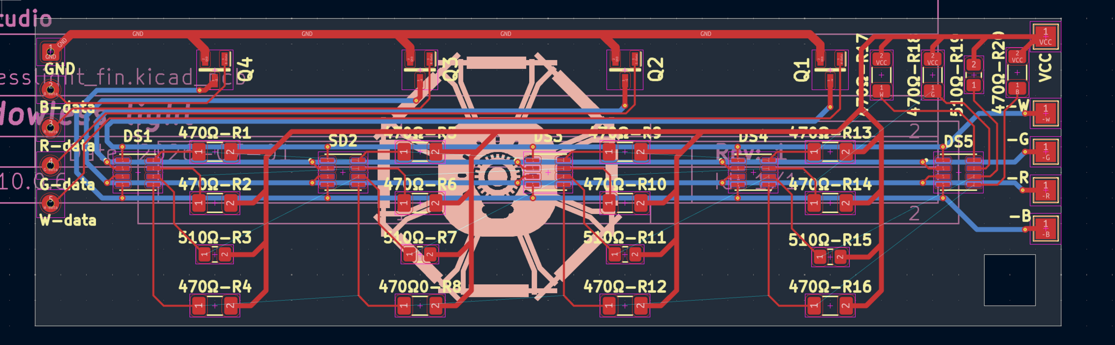
Shadowlesslight fin
- Size
- 100 × 30 mm
- Copper layers
- 2
- Thickness
- 1.6 mm
- Parts
- 35
- Nets
- 14
- Pads
- 102
- Tracks, vias
- 279, 28
- Routed
- Yes
- KiCad
- KiCad 10.0 (file 20260206)
- Created
- 9 Jul 2026
- Updated
- 20 Sep 2026
Overview
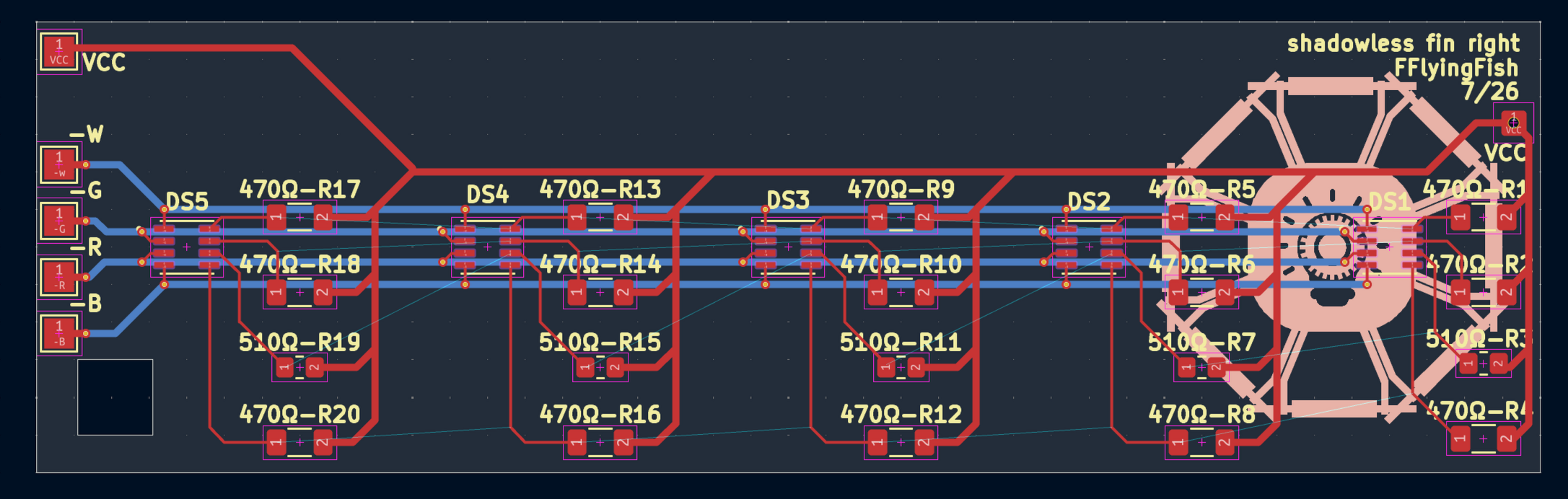
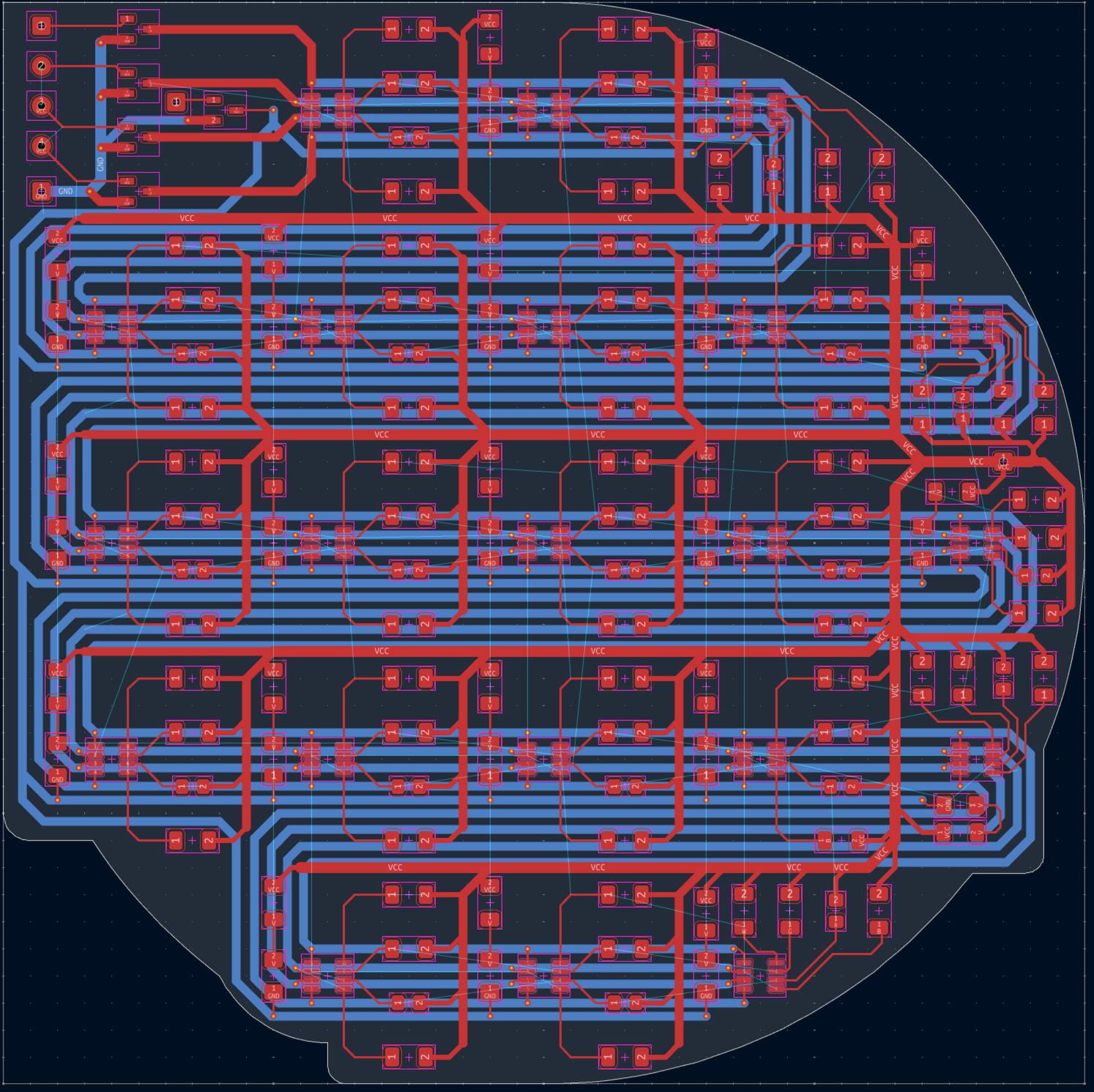
Shadowlesslight fin is an open-source printed circuit board by dinotiger01, from the dinotiger01/shadowless-light repository on GitHub. It is a 2-layer board of 100 × 30 mm with 35 parts on 14 nets, routed with 279 tracks and 28 vias.
README
README.mdshadowless-light
if you are a Stardance reviewer i messed up when doing the ship it has the wrong banner and video


description
demo video: https://youtu.be/H-r51vnOVfs
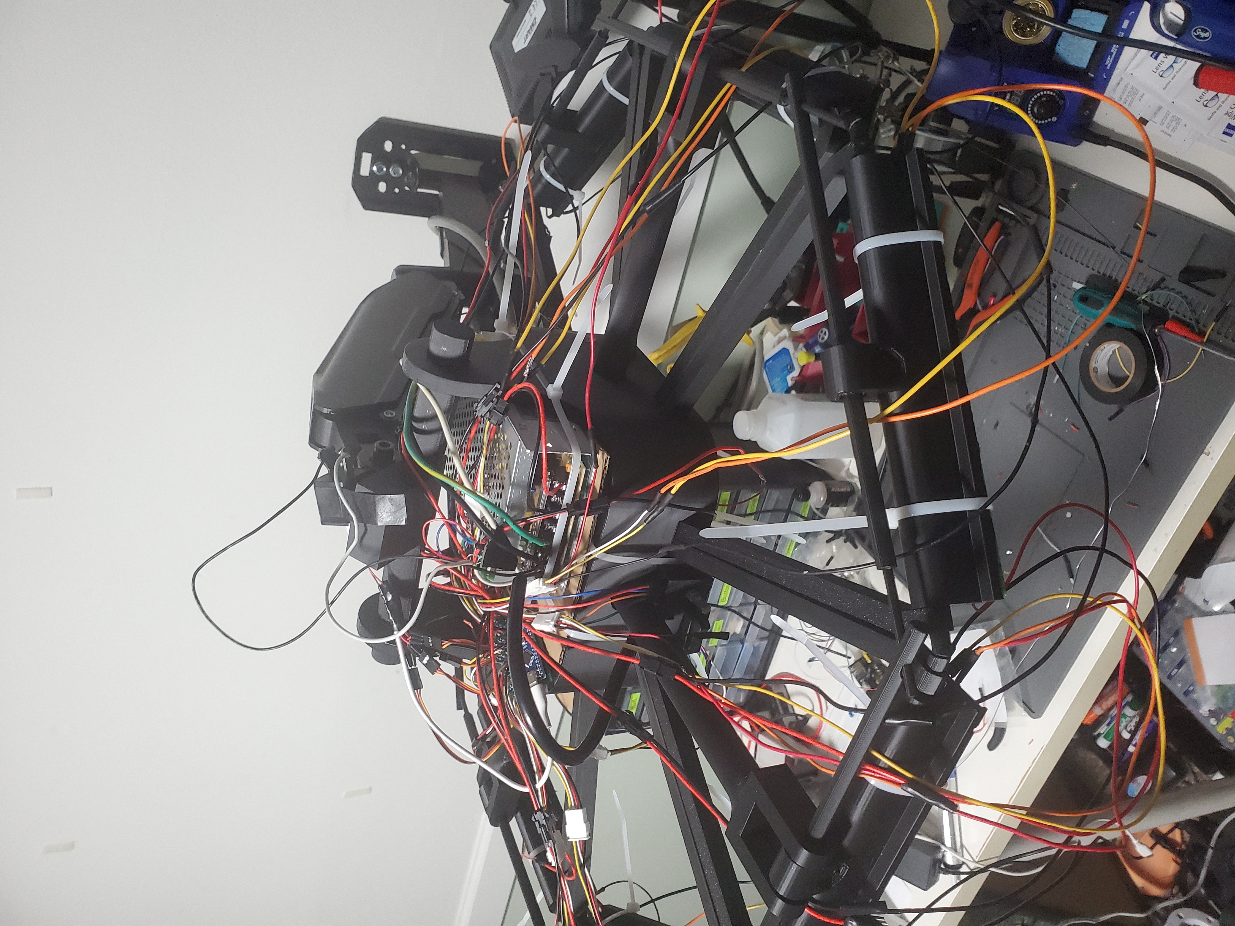
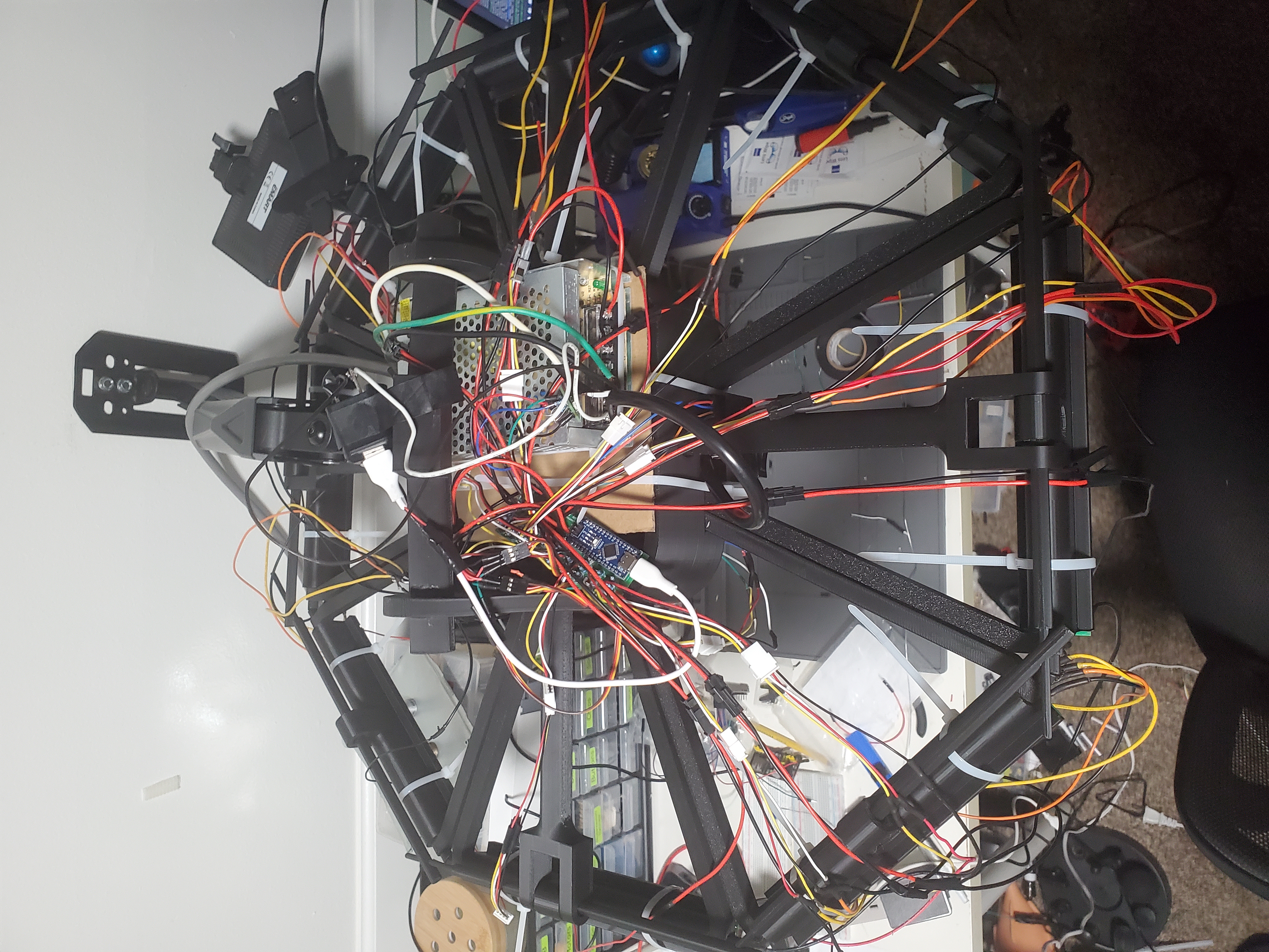
this is a desk light designed to not cast a shadow to make working on fine details easier
it works by having a main light then there is octogon ring around it that has lights and will tilt in and out to make sure every spot has at least one light on it
| regular light | shadowless ligh |
|---|---|
![]() | ![]() |
use cases
- soldering
- painting fine detail
- just like any kinda of work tbh
features
- btight
- RGBW
- UV
- adjustable lights
- blind yourself
assembly
i cover this in the yt video a lot better
3d print
settings:
plastic: pla
supports: trees
layer hight: 0.28mm
nozzle: 0.4mm
nozzle temp: 210°C
bed temp: 60°C
infill: 15%
| number | name |
|---|---|
| 1 | hook |
| 1 | main |
| 16 | supports |
| 8 | light |
| 8 | pivoit |
| 8 | push |
| 4 | servo |
| 16 | pin |
| 1 | cover |
wall
attatch the stand to the wall the instructions are on the box
3d print assembly
- remove suports
- put the hook on stand
- place the main thing on the hook
- place all the 16 suports in the main thing and secure it with the pins
- thread the pivots throught the suports and the lights to make an octogon
- put the servos through the big holes in the main thing
- then thread the push through the top of the light and the servo
- then the goes on top of the main thing
pcbs
| number | name |
|---|---|
| 8 | left wing |
| 8 | right wing |
| 1 | main |
| 1 | indicator |
| 1 | motherboard |
soldering
350 c recomended
- solder the 1 left wing light
- solder the 1 right wing light
- use the pad on the side to hold them togeather
- solder wires to the sides of the pcb
- repeate x 8
- main board
- RGBW the uv
- one of the lights needs some help
- mother board
- the v line is a cut power cable
- indicator
arduino
you need to use adruino ide to upload the script to the arduino nano
servos :(
so i forgot about the servo when making the pcb so there isnt a convinent break out for it so you need to solder a wire to pin 7 directly then split the wire in to 4 then thats the data wire for the servos and the gnd and power come direcly from the power suply also i think my servos are too weak so they wernt able to actualy do anyyhing
assembling electronics
- wings
- zip tie just like every thing
- then do that 8 times
- main
- you guesed it zip ties
- plug in all the things
- power supply
- connect a 120v ac up to the main thing
- connect one side to the switch on the front and the other side to one on the things on the 12v rectifer
- this is another thing i forgot to add to the pcb connect the 12v output to the power wires on the mother board
- now for the 5v if you have a buck dc to dc converter use that i didnt so i did this
- connect a wall 5v rectifyer in parralel with the 120vac then plug that in to the the arduino with a usb to usbc
- however we need to cut this wire then split it in to a bunch of things so that we can power the servos
documantation
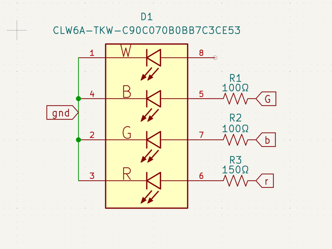
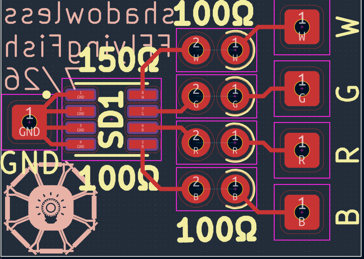
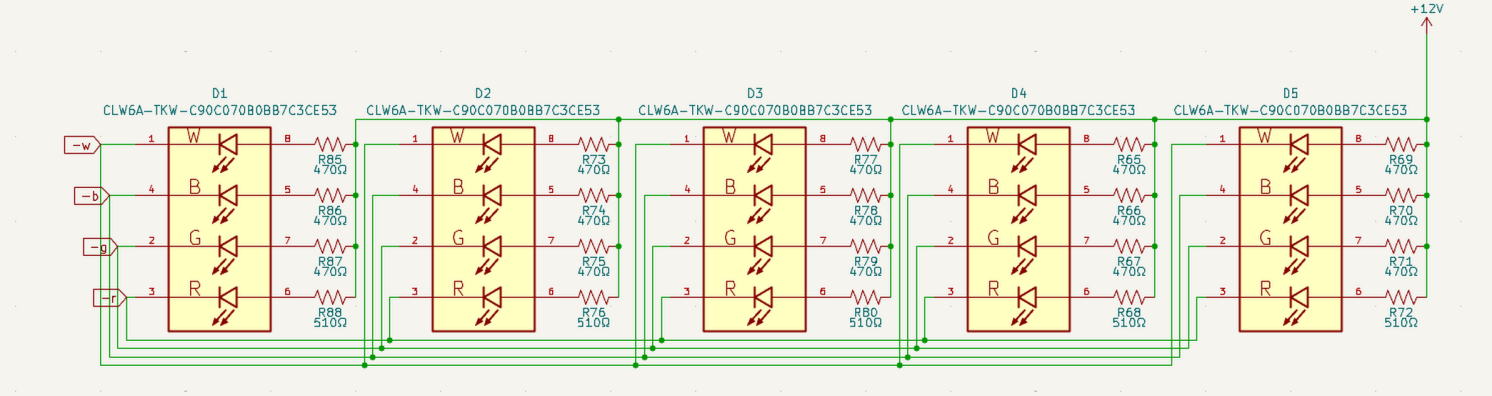
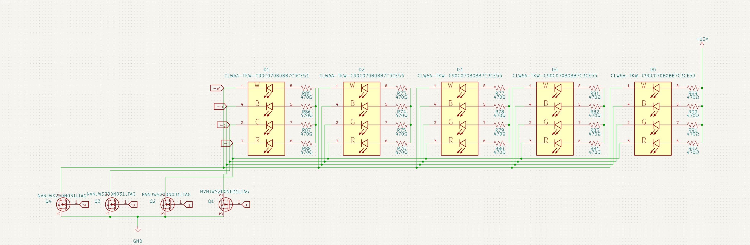
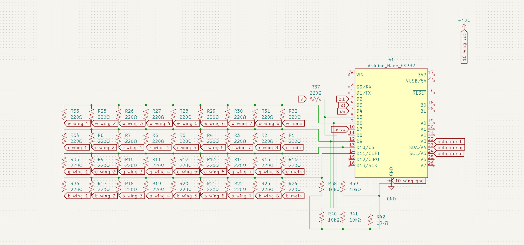
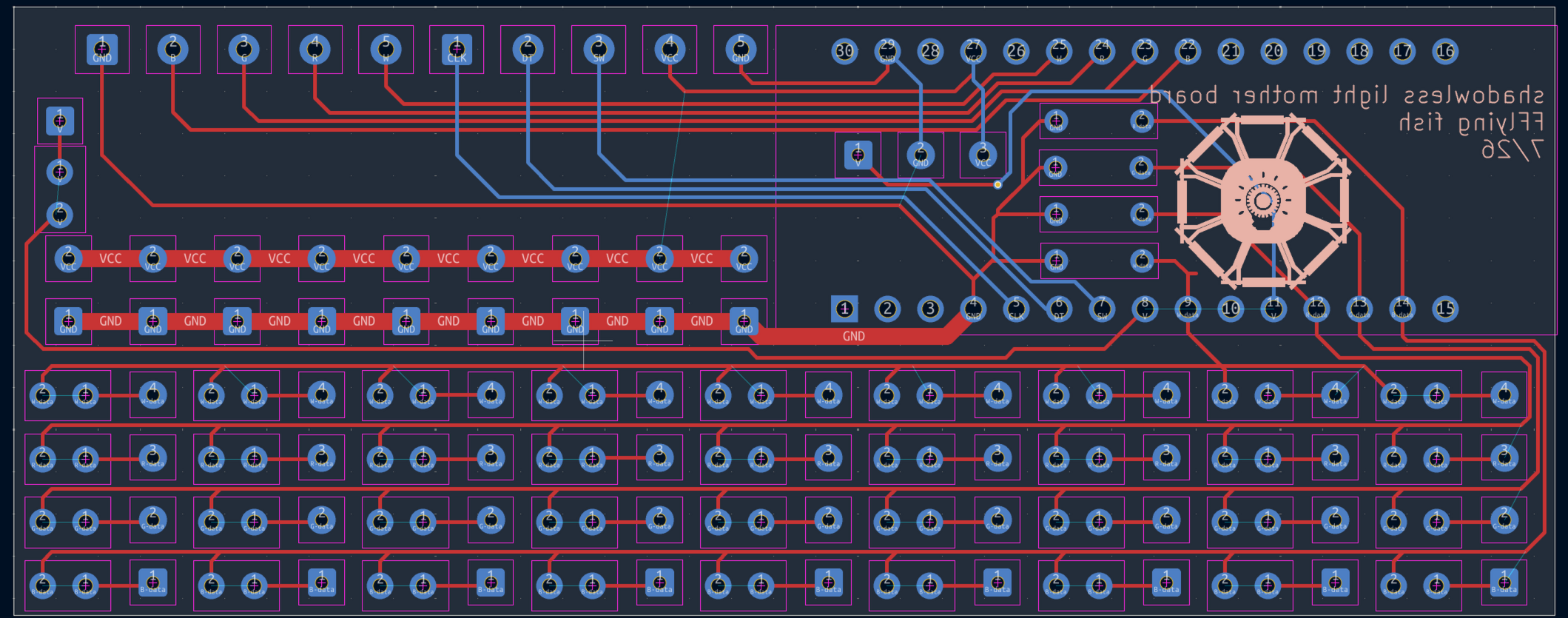
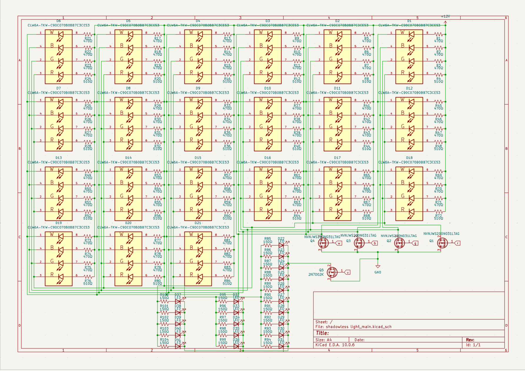
- schemadic
- indicator this is used to show if it is on and what value you are adjusting


- right wing
-
-
- left wing
-
-
- motherboard
-
-
- main
-
-
- voltage stuff
- lights are running at 12v
- each light runs at 20mA there is 4 lights in eash light there are 101 lights so 404 individual light + the 20 uv lights all run at 20mA or 0.02A * 424 = 8.48A
- the 12 has 10A to cover it all
- lumins alot
- red 4.8 lumens
- green 10.7 lumens
- blue 2.2 lumens
- 10.7 lumens
- 28.4 lumens per light X 101 = 248.4 lumens at max britness
- it is suposed to sit about 600mm off your desk
- its about 600mm in total witch ngl i think is too big i might make a smaler one in the futger
extra
- i am like really bad ar soldering so like half the light dont work
Parts
35| Qty | Value | Footprint | References |
|---|---|---|---|
| 15 | R_1206_3216Metric_Pad1.30x1.75mm_HandSolder | Resistor_SMD:R_1206_3216Metric_Pad1.30x1.75mm_HandSolder | 470Ω-R1, 470Ω-R2, 470Ω-R4, 470Ω-R5, 470Ω-R6, 470Ω-R9, 470Ω-R10, 470Ω-R12, 470Ω-R13, 470Ω-R14, 470Ω-R16, 470Ω-R17, 470Ω-R18, 470Ω-R20, 470Ω0-R8 |
| 5 | LED_CLW6A_RGBW | imports:LED_CLW6A_RGBW | DS1, DS3, DS4, DS5, SD2 |
| 5 | R_0805_2012Metric_Pad1.20x1.40mm_HandSolder | Resistor_SMD:R_0805_2012Metric_Pad1.20x1.40mm_HandSolder | 510Ω-R3, 510Ω-R7, 510Ω-R11, 510Ω-R15, 510Ω-R19 |
| 5 | TestPoint_Pad_2.0x2.0mm | TestPoint:TestPoint_Pad_2.0x2.0mm | -B, -G, -R, -W, VCC |
| 4 | SOT95P237X112-3N | imports:SOT95P237X112-3N | Q1, Q2, Q3, Q4 |
The 34 most common of 35 parts.
Questions
How big is the Shadowlesslight fin PCB?
It measures 100 × 30 mm and has 2 copper layers, 1.6 mm thick.
What parts does the Shadowlesslight fin use?
35 parts. The full list of its parts is on this page, with links to each part's symbol and footprint where PCBKit's library has them.
Where can I download the Shadowlesslight fin KiCad files?
From the dinotiger01/shadowless-light repository on GitHub, at the commit this page was made from: the board is pcb/kicad/shadowless light fin left/shadowlesslight_fin.kicad_pcb and its schematic pcb/kicad/shadowless light indicator/shadowless lightindicator.kicad_sch. PCBKit opens the board in the browser, with nothing to install.
Can I use the Shadowlesslight fin design in my own project?
Its repository states no licence, so its author keeps all rights: ask dinotiger01 before reusing the design.
More from dinotiger01/shadowless-light
4- 2 layers96.3 × 100 mm

- 2 layers91.3 × 36 mm

- 2 layers100 × 30 mm

- 2 layers17.5 × 12.5 mm

Similar boards
- 2 layers97.2 × 59.1 mm

ArmLEDsPrototype
hackclub/OnBoard
💡 Join 1,000 teenagers and make your first PCB with a $100 grant!
35 parts915 - 2 layers62 × 42 mm

- 2 layers75 × 26 mm

DIY detector electron variant
ozel/DIY_particle_detector
A mobile low-cost spectrometer for measuring radioactivity and the energy of ionising radiation like alpha particles and electrons
35 parts558BSD-2-Clause - 2 layers45 × 25 mm

ReCamera Basically Board
Seeed-Studio/OSHW-reCamera-Series
reCamera is a series of open-source AI cameras.
35 parts495Apache-2.0 - 2 layers160.8 × 24.4 mm

- 2 layers75 × 50 mm

- 2 layers50 × 20.5 mm

- 2 layers50.5 × 67.1 mm