2 layers131.8 × 99.9 mm

 dilshan/rtc-lamp1
Real-time clock based automatic LED lamp
Rtc nightlight is an open-source printed circuit board by dilshan, from the dilshan/rtc-lamp repository on GitHub, published under the MIT licence. It is a 2-layer board with 33 parts on 29 nets, routed with 276 tracks and 12 vias.
It is built around the MAX232N, DS1307+ and LM7805, with the 2SC945, 6A10 and STP55NF06 among its other parts. Its parts include 11 capacitors, 6 resistors, 4 ICs, 4 connectors and 2 transistors. It belongs with the lEDs and displays boards and the PIC boards of this library.


This is real-time clock based automatic LED lamp which we originally designed to use as night light. This lamp can programmed to turn on and off at the specific time of the day. For example, it can program to turn on at 6 PM on each day and to turn off at 4 AM next day.
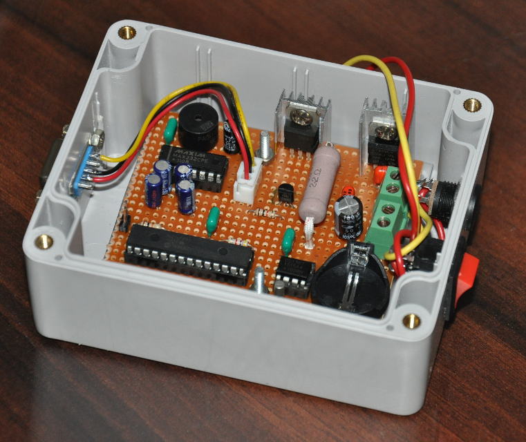
The core component of this project is PIC16F883 MCU and it's firmware is developed using MikroC Pro for PIC. We select this MCU because of it's 7 KB flash memory, I2C, UART, E2PROM and built-in 8-bit and 16-bit timers. In this system we use DS1307 RTC because of it's availability in the market and lower external component count.
This lamp is designed to work with commonly available 7W LED panels. In our prototype design we use 7W 24V warm-white LED module to test this system. To drive other LED modules change value of the R5 resistor of the current limiter circuit.

LED modules, heat-sink and lamp enclosures are now commonly available in the market but make sure to use good quality 24V - 28V LED module with this circuit. During our prototype we found lot of defective LED modules in the market.
This unit is designed to work with 24V - 3A power supply unit. 3V button cell is required as back power source of DS1307 RTC. Supplied PCB is designed to work with CR2025 or CR2032 type button cells.
For this project we use commonly available, less expensive electronic components and PCB is designed for "through-hole" type components.
Both Q1 (STP55N06) and U4 (LM7805) required heatsinks. If heatsink is shared between both devices make sure to use proper isolation in either Q1 or U4 (or both).
J3 to RS232 pin mapping for DB-9 connector is listed in below:
| J3 | DB9 |
|---|---|
| Pin 1 | Pin 2 |
| Pin 2 | Pin 3 |
| Pin 3 | Pin 5 |
PIC16F883 firmware is developed using MikroC Pro for PIC. Compiled HEX file is available at release section of this repository.
This system is designed to program using RS232 serial port. User can modify system time, light start and end times by connecting this system to any computer through RS232 serial port. To program and view system information user can use any serial terminal application like minicom, putty, etc. with baud rate of 9600.
Once system is connected to the host PC it can switch to programming mode by sending Enter or Space key stroke through the serial terminal.
If host PC is not equipped with serial port, use USB to RS232 converter cable / module. During our tests we use couple of USB to RS232 converters (such as FT232 and CH340) without any issues.
| Id | Component | Qty |
|---|---|---|
| U1 | PIC16F883-IP | 1 |
| U2 | DS1307 | 1 |
| U3 | MAX232 | 1 |
| U4 | LM7805 | 1 |
| Q1 | STP55NF06 | 1 |
| Q2 | 2SC945 | 1 |
| D1 | 6A10 | 1 |
| Y1 | 32.768 Crystal | 1 |
| BT1 | CR2025 or CR2032 battery holder with battery | 1 |
| R1, R2, R3 | 4.7K | 3 |
| R4, R6 | 10 K | 2 |
| R5 | 2.2R - 3W | 1 |
| C1 | 4.7 MFD / 16V | 1 |
| C2, C3, C4, C5 | 10MFD / 16V | 4 |
| C6 | 0.33MFD / 63V | 1 |
| C7, C9, C10, C11 | 0.1 MFD / 63V | 4 |
| C8 | 470 MFD / 35V | 1 |
| F1 | 12V 1A Fuse | 1 |
| L1 | VK200 - 3 turns | 1 |
| BZ1 | KXG1203C or 5V DC PCB mount buzzer | 1 |
| J1 | 2.54mm - 2 Way, 1 Row PCB header | 1 |
| J2 | 2.54mm - 3 Way, 1 Row PCB header | 1 |
| J3, J4 | 5.08mm - 2 Way PCB terminal block | 2 |
| 7W 24V/28V LED module and heatsink | 1 | |
| 3mm Red LED | 1 | |
| DC 50V Rocker switch | 1 | |
| DB9 Female Connector | 1 | |
| Panel Mount DC Power Socket | 1 | |
| TO-220 heatsink | 2 |
This is an open hardware project and all it's source code are released under the terms of MIT license. Schematics, PCB designs and other resources are released under the terms of Creative Commons Attribution 4.0 international license.
| Qty | Value | Footprint | References |
|---|---|---|---|
| 4 | 0.1MFD | Capacitor_THT:C_Disc_D8.0mm_W5.0mm_P5.00mm | C7, C9, C10, C11 |
| 4 | 10MFD | Capacitor_THT:CP_Radial_Tantal_D5.0mm_P5.00mm | C2, C3, C4, C5 |
| 3 | 4.7K | Resistor_THT:R_Axial_DIN0207_L6.3mm_D2.5mm_P10.16mm_Horizontal | R1, R2, R3 |
| 2 | 10K | Resistor_THT:R_Axial_DIN0207_L6.3mm_D2.5mm_P10.16mm_Horizontal | R4, R6 |
| 1 | 0.33MFD | Capacitor_THT:C_Disc_D16.0mm_W5.0mm_P10.00mm | C6 |
| 1 | 12V 1A | Fuse:Fuseholder_TR5_Littelfuse_No560_No460 | F1 |
| 1 | 2.2R | Resistor_THT:R_Axial_DIN0411_L9.9mm_D3.6mm_P12.70mm_Horizontal | R5 |
| 1 | 24V 3A IN | TerminalBlock_Phoenix:TerminalBlock_Phoenix_MKDS-3-2-5.08_1x02_P5.08mm_Horizontal | J4 |
| 1 | 2SC945 | Package_TO_SOT_THT:TO-92_Inline_Wide | Q2 |
| 1 | 32.768kHz | Crystal:Crystal_AT310_D3.0mm_L10.0mm_Horizontal | Y1 |
| 1 | 4.7MFD | Capacitor_THT:CP_Radial_Tantal_D5.0mm_P5.00mm | C1 |
| 1 | 470MFD | Capacitor_THT:CP_Radial_D10.0mm_P7.50mm | C8 |
| 1 | 6A10 | Diode_THT:D_DO-201AD_P15.24mm_Horizontal | D1 |
| 1 | 7W LED | TerminalBlock_Phoenix:TerminalBlock_Phoenix_MKDS-3-2-5.08_1x02_P5.08mm_Horizontal | J3 |
| 1 | Buzzer | Buzzer_Beeper:Buzzer_12x9.5RM7.6 | BZ1 |
| 1 | CR2032-HOLDER | Battery:BatteryHolder_Keystone_106_1x20mm | BT1 |
| 1 | DS1307+ | Package_DIP:DIP-8_W7.62mm_LongPads | U2 |
| 1 | IND-LED | Connector_PinHeader_2.54mm:PinHeader_1x02_P2.54mm_Vertical | J1 |
| 1 | LM7805 | Package_TO_SOT_THT:TO-220-3_Vertical | U4 |
| 1 | MAX232 | Package_DIP:DIP-16_W7.62mm_LongPads | U3 |
| 1 | PIC16F883-IP | Package_DIP:DIP-28_W7.62mm_LongPads | U1 |
| 1 | RS232 | Connector_PinHeader_2.54mm:PinHeader_1x03_P2.54mm_Vertical | J2 |
| 1 | STP55NF06 | Package_TO_SOT_THT:TO-220-3_Vertical | Q1 |
| 1 | VK200-3T | Inductor_THT:L_Axial_L7.0mm_D3.3mm_P2.54mm_Vertical_Fastron_MICC | L1 |

RocketryVT/active-drag-system
Eigen Library, cmake, and arm-none-eabi-gcc tooling required for successful build.


bpmine/minou_uino
Les programmes de cette base gèrent la cabane de notre minou (voir images suivantes).

chdsolinap/ece-projects
ECE hardware and electronics projects — PCB design, circuit prototypes, and embedded systems built at PLM.


33 parts, built around the MAX232N, DS1307+, LM7805 and 2SC945. The full list of its parts is on this page, with links to each part's symbol and footprint where PCBKit's library has them.
From the dilshan/rtc-lamp repository on GitHub, at the commit this page was made from: the board is rtc-nightlight-kicad/rtc-nightlight.kicad_pcb. PCBKit opens the board in the browser, with nothing to install.
Its repository publishes it under the MIT licence: you may reuse it on that licence's terms (keep the author's notice, and for a copyleft licence share your changes alike).