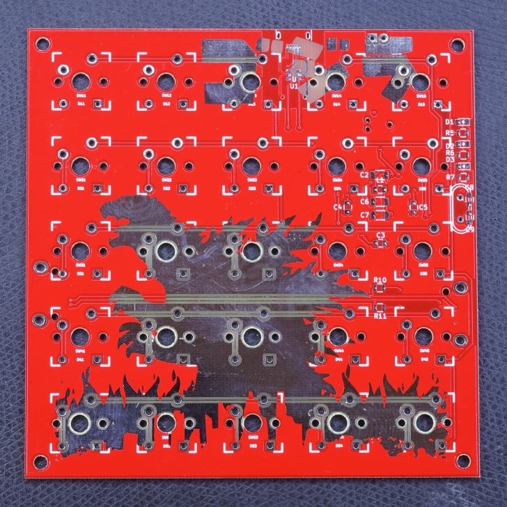
5x5 is an open-source printed circuit board by dijkstrw, from the dijkstrw/5x5 repository on GitHub. It is a 2-layer board of 100 × 100 mm with 92 parts on 62 nets, routed with 494 tracks and 44 vias.
It is built around the STM32F103C8T6 and LD1117S33CTR-HXY. Its parts include 28 diodes, 25 switches, 13 capacitors, 11 resistors and 4 connectors. It belongs with the keyboards and input boards and the STM32 boards of this library.
This is my first custom keyboard, a 5x5 cherry mx matrix based on the STM32F1
with libopencm3. The project contains firmware, schematics and a board layout
in kicad.
This project is intended as a platform for custom keyboard development. It
supports:
usb keyboard scancodes
bios boot and nkro
system / consumer codes
generation of mouse events
usb serial interface
an automouse mode for fast-clicking
programmable macro keys via serial
storing current configuration in "userflash"
The board is programmed using a 6-pin TagConnect, that must be wired
to a STM Discovery SWD/STLink programming port.
Building
text
git submodule init
git submodule update
make -C libopencm3
make
Features
Keyboards
The board provides 3 types of keyboards via different usb
endpoints.
The first is the usb standard bios keyboard definition, which
allows the keyboard also to emit key codes to hosts with limited
usb hid support. (This used to be the case in <2015 style bioses,
hence the name.)
The second keyboard is a n-key-rollover, which exposes a keyboard
that allows 224 usb keyboard scancodes to be pressed
simultaneously. Also, because we do not need to adhere to the bios
boot standard, this endpoint's interval can set much lower = it
types much faster.
The third keyboard can emit so called consumer and system
codes. Example consumer key codes are PLAY, PAUSE, but also MARK,
CLEARMARK, REPEATFROMMARK. So everything the typical multimedia
keys emit and then some.
Mouse
Operate the rodent from your keyboard! There is support for x, y, 5
buttons and a vertical and horizontal scrollwheel action.
Serial
The board exposes a serial port for logging, and
configuration. Commands available are:
text
? - show a terse description of available commands.

i - show usb info strings; contains the git-describe tag of the
    current firmware, so mission critical to some, useless to
    everybody else.

d - dump the keymap(s).

K - redefine a key in the keymap, takes a hexadecimal argument of
    the form <layer><row><column><type><arg1><arg2><arg3>, with each
    argument being 2 digits long.

m - clear all macro keys.

M - define one macro key, takes an argument of the form
    <number><oftenusedstring>. The number is a two hexdigits, the
    string can be upto 32 7-bit ascii chars long and is terminated
    with a newline.

n - set keyboard mode to bios (default).

N - set keyboard mode to nkro.

R - read configuration from flash
Command interpretation starts after receiving a newline.
Automouse
Automouse is a mouse clicker, with optional speed setting and wiggle
amounts. This allows you to click real fast, and wiggle the mouse
while using your hands for something else.
Macros
Macros set via serial are lost at power off unless the configuration
is written to flash. Loading from flash happens automatically at
powerup.
The strings that you provide via serial need to be translated into usb
keycodes, so currently only 7-bit ascii strings are supported.
The initial newline is a trick to make sure our M will be considered
the start of a command, no matter what has been put to the serial
before by you, some driver or the os.
This particular example defines the macro for macro key number 1.
You need to have a macro key 1 in your keymap, otherwise you have
nothing to trigger the macro.
It measures 100 × 100 mm and has 2 copper layers, 1.6 mm thick.
What parts does the 5x5 use?
92 parts, built around the STM32F103C8T6 and LD1117S33CTR-HXY. The full list of its parts is on this page, with links to each part's symbol and footprint where PCBKit's library has them.
Where can I download the 5x5 KiCad files?
From the dijkstrw/5x5 repository on GitHub, at the commit this page was made from: the board is schematic/5x5.kicad_pcb. PCBKit opens the board in the browser, with nothing to install.
Can I use the 5x5 design in my own project?
Its repository states no licence, so its author keeps all rights: ask dijkstrw before reusing the design.
Původní záměr byl použít ZIF socket, ten se však pro pDIP8 pouzdro prakticky nevyrábí. Zvolil jsem proto přesnou patici z doporučených komponent. Klíčovými kritérii byl nízký odpor kontaktů a zlaté pokovení pinů.
Hardware - dingoPDM is an open source, affordable automotive PDM (Power Distribution Module). Pre-assembled and tested units are available or the design can be used to build a DIY version.