
2 layers410 × 128.5 mm
Franklin ace-1000-keyboard
osiweb/unified_retro_keyboard
Project to provide keyboard replacements for various classic computers, as well as classic ASCII keyboard
169 parts122

 dhillon-m/custom-keyboard
ZMK firmware for the BHOO-75 wireless keyboard and BHOO-20 numpad with OLED (nice!nano v2, split)
Bhoo 75 is an open-source printed circuit board by dhillon-m, from the dhillon-m/custom-keyboard repository on GitHub, published under the MIT licence. It is a 2-layer board of 306.4 × 122.2 mm with 169 parts on 111 nets, routed with 512 tracks and 18 vias.
Its parts include 84 diodes, 84 switches and 1 IC. It belongs with the keyboards and input and lEDs and displays boards and the nRF52 and nRF5x boards of this library.



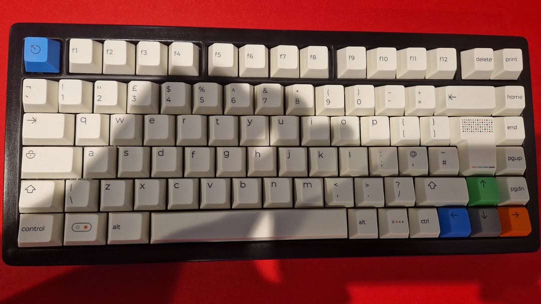
A custom wireless keyboard setup with two parts. This repo has the ZMK firmware, the KiCad PCB and the case CAD.
| Device | Role | Description |
|---|---|---|
| BHOO-75 | Split central | Custom PCB, 75% ISO (UK) with an F-row and arrow cluster. 84 keys. |
| BHOO-20 | Split peripheral | Handwired numpad with a 128×64 SSD1306 OLED (WIP). 19 keys. |
Both run on a nice!nano v2 (nRF52840). The BHOO-75 pairs with the host over Bluetooth or USB. The BHOO-20 connects to the BHOO-75 as a ZMK split peripheral, so both boards share one keymap and appear to the computer as a single keyboard.
bhoo_75.keymap.zmk-locales (keys_en_gb.h).hardware/. See Hardware.settings_reset image is built too.Not working yet. Nothing shows on the screen at the moment. The code and images below are the design being worked towards, not the current behaviour.
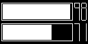
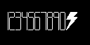
The planned screen shows two battery bars, one per device. Each bar will fill 1 px per percent, with a hand-drawn 5×9 percentage readout next to it. At 100% the number turns into a lightning bolt. The drawing is done directly on an LVGL canvas in battery_screen.c.
zmk_battery_state_changed.segment-remap and com-invdir.CONFIG_ZMK_DISPLAY_BLANK_ON_IDLE).bhoo_battery_set_central() exists, but nothing sends the central's battery level to the peripheral yet.BHOO-75
Esc   F1  F2  F3  F4  F5  F6  F7  F8  F9  F10 F11 F12 Del  PrtSc
`     1   2   3   4   5   6   7   8   9   0   -   =   Bksp Home
Tab   Q   W   E   R   T   Y   U   I   O   P   [   ]        End
Caps  A   S   D   F   G   H   J   K   L   ;   '   #   Ent  PgUp
Shift \   Z   X   C   V   B   N   M   ,   .   /   Shift ↑  PgDn
Ctrl  Win Alt         Space           Alt Fn  Ctrl  ←   ↓   →
BHOO-20
            ┌─────┬─────┐
            │  —  │  —  │
┌─────┬─────┼─────┼─────┤
│ Num │  /  │  *  │  -  │
├─────┼─────┼─────┼─────┤
│  7  │  8  │  9  │     │
├─────┼─────┼─────┤  +  │
│  4  │  5  │  6  │     │
├─────┼─────┼─────┼─────┤
│  1  │  2  │  3  │     │
├─────┴─────┼─────┤ Ent │
│     0     │  .  │     │
└───────────┴─────┴─────┘
The two — keys at the top are unassigned (&none).
Fn)| Key | Action |
|---|---|
| F1–F4 | Select Bluetooth profile 0–3 |
| F5 | Clear the current profile's bond |
| F6 | Enter bootloader (BHOO-75) |
.
├── build.yaml                       # Build matrix (board + shield combos)
├── .github/workflows/build.yml      # Uses ZMK's reusable build workflow (v0.2)
├── config/
│   ├── west.yml                     # Pins ZMK v0.2 + zmk-locales
│   └── boards/shields/
│       ├── bhoo_75/                 # Main keyboard: central
│       │   ├── bhoo_75.overlay      # 6×15 GPIO matrix + transform (padded to 19 cols)
│       │   ├── bhoo_75.keymap       # Keymap for both devices
│       │   └── bhoo_75.conf         # Split central
│       └── bhoo_20/                 # Numpad: peripheral
│           ├── bhoo_20.overlay      # 6×4 GPIO matrix, SSD1306 on i2c0
│           ├── bhoo_20.conf         # Display, battery, LVGL canvas
│           ├── battery_screen.c     # Custom status screen (WIP)
│           └── CMakeLists.txt
├── hardware/
│   ├── bhoo_75/pcb/                 # KiCad 8 PCB project
│   ├── bhoo_75/case/                # Top case, bottom case, plate, foot (STEP)
│   └── bhoo_20/case/                # Numpad case parts (STL)
├── docs/images/                     # Photos, renders, OLED mock-ups
└── zephyr/module.ymlbhoo_75-nice_nano_v2-zmk.uf2bhoo_20-nice_nano_v2-zmk.uf2settings_reset-nice_nano_v2-zmk.uf2With a ZMK development environment set up:
west build -s zmk/app -d build/bhoo_75 -b nice_nano_v2 -- \
  -DSHIELD=bhoo_75 -DZMK_CONFIG="$(pwd)/config"

west build -s zmk/app -d build/bhoo_20 -b nice_nano_v2 -- \
-DSHIELD=bhoo_20 -DZMK_CONFIG="$(pwd)/config"NICENANO)..uf2 onto the drive. It reboots on its own when the copy finishes.Pairing problems? Flash settings_reset to both boards, then reflash the normal firmware. This clears stale split and Bluetooth bonds. Afterwards, remove the keyboard from your computer's Bluetooth list and pair it again.
The BHOO-75 uses a two-layer PCB designed in KiCad 8. It's about 336 mm wide, with:
| Layout in KiCad | Bare board |
|---|---|
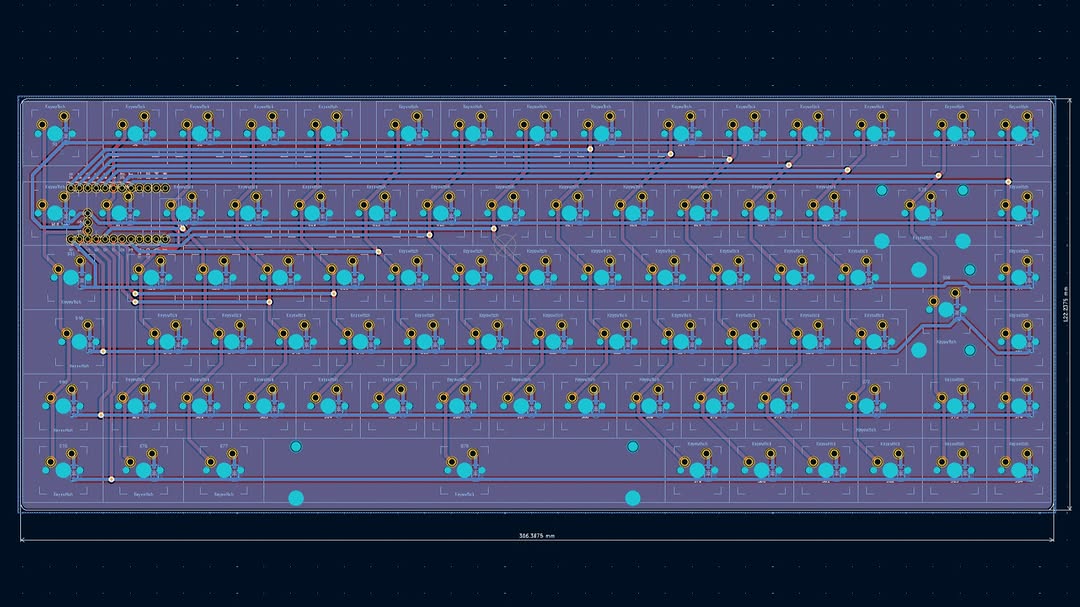 | 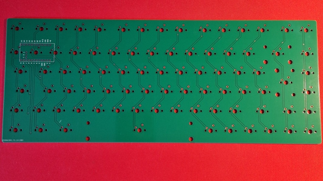 |
| Populated (underside) | Diodes up close |
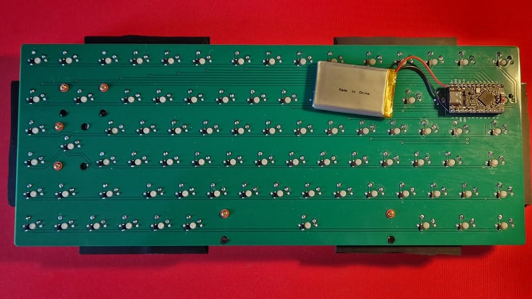 | 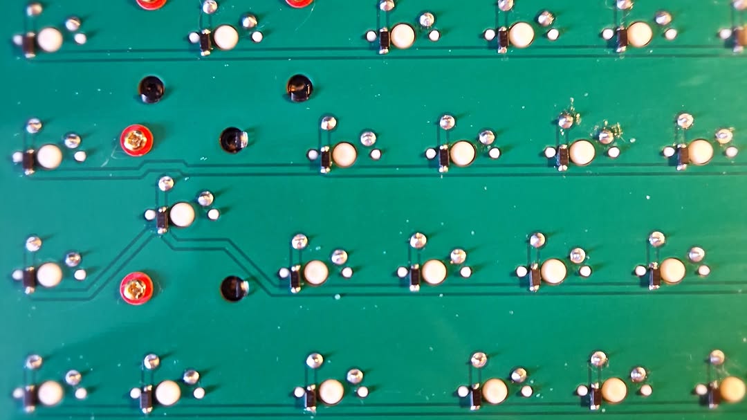 |
| File | Description |
|---|---|
hardware/bhoo_75/pcb/ | KiCad 8 project: schematic (PCB.kicad_sch) and board (PCB.kicad_pcb) |
hardware/bhoo_75/case/Top Case.step | Top case |
hardware/bhoo_75/case/Bottom Case.step | Bottom case |
hardware/bhoo_75/case/Plate.step | Switch plate |
hardware/bhoo_75/case/Foot.step | Foot |
Opening the PCB in KiCad: footprints are stored inside the board file, so the PCB opens without any extra libraries. To edit the schematic symbols or see the 3D view, you also need:
SCOTTOKEEBS_KICAD path variable to wherever you put it.MX_Solderable switch footprints.The switch 3D models point to a file on the original author's PC, so they won't show in the 3D viewer.
The BHOO-20 is handwired: switches are wired directly into a 6 × 4 matrix with diodes, no PCB. Printable case parts are in hardware/bhoo_20/case/:
Top Case.stlBottom Case.stlPlate.stlFoot.stl| Board | Matrix | Diodes | Rows (GPIO) | Columns (GPIO) |
|---|---|---|---|---|
| BHOO-75 | 6 × 15 | col2row | P1.02 P1.07 P1.06 P1.04 P0.11 P1.00 | P1.01 P0.02 P0.24 P0.22 P0.20 P0.17 P0.08 P0.06 P0.09 P0.10 P1.11 P1.13 P1.15 P0.29 P0.31 |
| BHOO-20 | 6 × 4 | col2row | P0.09 P0.10 P1.11 P1.13 P1.15 P0.02 | P0.24 P1.00 P0.11 P1.04 |
The BHOO-20 OLED is an SSD1306 at I²C address 0x3C on i2c0, using the nice!nano default SDA/SCL pins.
The BHOO-75 matrix transform declares 19 columns. Columns 15–18 are virtual padding that reserve key positions 0–18 for the BHOO-20, so a single keymap can cover both devices.
Everything in this repository, including the firmware, the PCB and the case CAD, is released under the MIT License.
| Qty | Value | Footprint | References |
|---|---|---|---|
| 84 | Diode | ScottoKeebs_Components:Diode_SOD-123 | D1, D2, D10, D11, D12, D13, D14, D15, D16, D17, D18, D19, D20, D21, D22, D23 +68 |
| 74 | Keyswitch | MX_Solderable:MX-Solderable-1U | S1, S2, S10, S11, S12, S13, S14, S15, S16, S17, S18, S19, S20, S21, S22, S23 +58 |
| 4 | Keyswitch | MX_Solderable:MX-Solderable-1.25U | S60, S75, S76, S77 |
| 2 | Keyswitch | MX_Solderable:MX-Solderable-1.75U | S45, S72 |
| 1 | Keyswitch | MX_Solderable:MX-Solderable-ISO | S58 |
| 1 | Keyswitch | MX_Solderable:MX-Solderable-6.25U | S78 |
| 1 | Keyswitch | MX_Solderable:MX-Solderable-1.5U | S31 |
| 1 | Keyswitch | MX_Solderable:MX-Solderable-2U | S29 |
| 1 | Nice_Nano_V2 | ScottoKeebs_MCU:Nice_Nano_V2 | U1 |
osiweb/unified_retro_keyboard
Project to provide keyboard replacements for various classic computers, as well as classic ASCII keyboard


NuttyShell/NuttyBadge
NuttyBadge: A NuttyShell crafted multi-tool. Opensourced Hardawre and Software

cbskii/storyboard-keyboard
5x12 split ortholinear keyboard with an E-INK display


yyevax/xavient-kbd
xavient is a thin split mechanical keyboard that does not sacrifice repairability and upgradablility. Inspired by the sleek design of the Corne-ish Zen but with hotswappalbe switches and components.

pedalboard/pedalboard-hw
pedalboard audio midi processor open hardware

ymkn/YuTofu
YuTofu is an unofficial compatible PCB for the well-known custom keyboard Tofu60 2.0.
It measures 306.4 × 122.2 mm and has 2 copper layers, 1.6 mm thick.
169 parts. The full list of its parts is on this page, with links to each part's symbol and footprint where PCBKit's library has them.
From the dhillon-m/custom-keyboard repository on GitHub, at the commit this page was made from: the board is hardware/bhoo_75/pcb/PCB.kicad_pcb and its schematic hardware/bhoo_75/pcb/PCB.kicad_sch. PCBKit opens the board in the browser, with nothing to install.
Its repository publishes it under the MIT licence: you may reuse it on that licence's terms (keep the author's notice, and for a copyleft licence share your changes alike).