2 layers40 × 30 mm
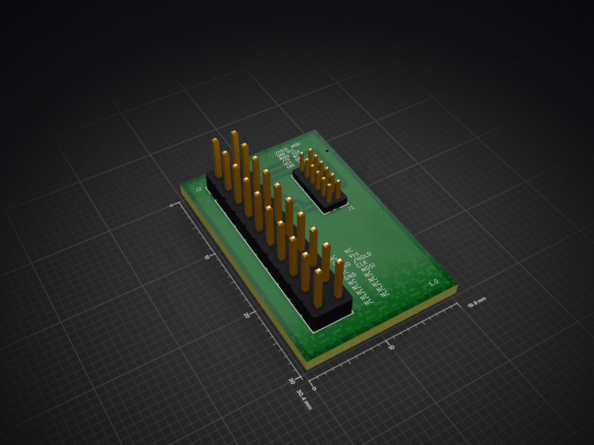
 dhendrix/dediprog2up7
KiCad project for Dediprog 20-pin SF600/EM100 to UP Squared/Xtreme 12-pin adapter
Dediprog2up is an open-source printed circuit board by dhendrix, from the dhendrix/dediprog2up repository on GitHub, published under the CC-BY-4.0 licence. It is a 2-layer board of 19.9 × 30.4 mm with 3 parts on 21 nets, routed with 57 tracks and 2 vias.
It belongs with the interfaces and adapters boards of this library.
This is an adapter intended to make firmware development easier on UP Xtreme and UP Squared motherboards using Dediprog SF600 and EM100.
This project started as I was thinking about playing with the system firmware (BIOS) on the UP Xtreme and trying to do a coreboot port. I had limited success at creating a custom cable with a 12-pin header on one side and a 20-pin header on the other to fit on a Dediprog ADP-SF600-254-TO-127-CB. It was difficult to split a fine-pitch ribbon cable and when I finally got one working it could only operate at 1.5MHz.
Using this adapter board I was able to read and write the ROM using an SF600 at 24MHz, which is also fast enough to use an EM100 for SPI flash emulation.

The UP wiki has a good diagram of the header: https://wiki.up-community.org/BIOS_chip_flashing_on_UP_Squared
I probed all the pins to verify the UP wiki's pinout. I'm still not sure which pin is write-protect or if the extra 4 pins are used for anything (the flash chip only has 8 pins), so if you happen to know feel free to send a PR to update this README or file an issue to let me know!
The header is 2x6, pitch is 1.27mm.
| Pin | Signal | Signal | Pin |
|---|---|---|---|
| 1 | GND | GND | 2 |
| 3 | GND | VCC | 4 |
| 5 | VCC | /CS | 6 |
| 7 | CLK | MISO | 8 |
| 9 | VCC | GND | 10 |
| 11 | MOSI | /HOLD | 12 |
The header is 2x10, pitch is 2.54mm
The pinout is printed on the device, but here is a simplified version for our purposes:
| Pin | Signal | Signal | Pin |
|---|---|---|---|
| 1 | NC | NC | 2 |
| 3 | /CS | VCC | 4 |
| 5 | MISO | /HOLD | 6 |
| 7 | NC | CLK | 8 |
| 9 | GND | MOSI | 10 |
| 11 | NC | NC | 12 |
| 13 | NC | NC | 14 |
| 15 | NC | NC | 16 |
| 17 | NC | NC | 18 |
| 19 | NC | NC | 20 |
There are a few online PCB fabrication companies. For this project I used Oshpark since they make it super-easy to order boards that were made with KiCad. Just upload the .kicad_pcb file to their website and they'll do the rest.
Here is a project page at Oshpark where you can order directly: https://oshpark.com/shared_projects/HCAx2AVW
12-pin header to plug cable into: https://www.chipquik.com/store/product_info.php?products_id=1900044
20-pin connector to plug into SF600/EM100: https://www.digikey.com/en/products/detail/sullins-connector-solutions/SFH11-PBPC-D10-ST-BK/1990090

Top view with headers soldered on

Bottom view with headers soldered on
One thing to keep in mind when working with SPI flash is that shorter cables are better. Up to 4 inches / 10 centimeters is generally OK, but above that you may need to slow down your programmer's clock frequency. If you can use a shorter cable then it's recommended that you do so.
The UP Xtreme's pin header is squeezed in between the HDMI/DP connector and the RTC battery header. You'll likely need to cut (e.g. using a Dremel) the sides of the receptacle on one end of the cable - be sure you do so on the side that plug into the board. This unfortunately makes it easy for the receptacle to fall apart, so be careful when handling the cable once it's plugged in.
12-pin 1.27mm pitch cables are somewhat rare and expensive, but come with some assurance of quality so it's not a bad idea to have one.
Here is a pre-made cable on Mouser: https://www.mouser.com/ProductDetail/200-FFSD06D04.0001N
It's somewhat easier to find the parts needed to make a 12-pin 1.27mm pitch cable than finding a premade cable.
Ribbon cable: https://www.mouser.com/ProductDetail/Wurth-Elektronik/63911215521CAB?qs=rrS6PyfT74fhArRJ3tCNFA%3D%3D
IDC header: https://www.mouser.com/ProductDetail/Harwin/M50-3300642?qs=lPIp2VBpF5j6R5jWq4Rd4A%3D%3D
The flash chip on the UP Xtreme is a 1.8V W25Q256JWEQ. The flash chip on the UP Squared is a 1.8V W25Q128FW (according to the UP Wiki).
I've been able to successfully read it at 24MHz which is the highest speed the SF600 supports. It is recommended to read the chip several times and diff the output to ensure consistent readings. Inconsistent readings may indicate that your cable is too long or that there is a quality issue with your cable or soldering.
Here is how to read it using flashrom:
flashrom -p dediprog:voltage=1.8,spispeed=24M -r foo.binA similar adapter for UP boards intended to work with Dediprog hardware: https://github.com/skiselev/up-dediprog-adapter
The qspimux project has adapters for several popular NOR flash sockets and adds isolatation circuitry to eliminate potential errors while also making it suitable for programmers that are always-on: https://github.com/felixheld/qspimux
| Qty | Value | Footprint | References |
|---|---|---|---|
| 1 | Conn_02x10_Odd_Even | Connector_PinHeader_2.54mm:PinHeader_2x10_P2.54mm_Vertical | J2 |
| 1 | Conn_02x6_Odd_Even | Connector_PinHeader_1.27mm:PinHeader_2x06_P1.27mm_Vertical | J1 |
| 1 | Net-Tie_2 | NetTie:NetTie-2_SMD_Pad0.5mm | GND1 |
It measures 19.9 × 30.4 mm and has 2 copper layers, 1.6 mm thick.
3 parts. The full list of its parts is on this page, with links to each part's symbol and footprint where PCBKit's library has them.
From the dhendrix/dediprog2up repository on GitHub, at the commit this page was made from: the board is dediprog2up.kicad_pcb. PCBKit opens the board in the browser, with nothing to install.
Its repository publishes it under the CC-BY-4.0 licence: you may reuse it on that licence's terms (keep the author's notice, and for a copyleft licence share your changes alike).

hzeller/rpi-rgb-led-matrix
Controlling up to three chains of 64x64, 32x32, 16x32 or similar RGB LED displays using Raspberry Pi GPIO


atopile/atopile
Design circuit boards with code! ✨ Get software-like design reuse 🚀, validation, version control and collaboration in hardware; starting with electronics ⚡️


hackclub/sprig
🍃 Learn to code by making games in a JavaScript web-based game editor.