

2 layers68.6 × 76.2 mm

This directory contains the primary hardware design and layout files for the Miniature Programmable Power Supply (Team TUE-20).
CPU- is an open-source printed circuit board by dharmandermina88-wq, from the dharmandermina88-wq/CPU- repository on GitHub. It is a 2-layer board of 68.6 × 76.2 mm with 26 parts on 13 nets, routed with 68 tracks and 34 vias.
It is built around the MC34063ECN. Its parts include 14 connectors, 3 capacitors, 2 resistors, 1 IC and 1 diode.
This directory contains the primary hardware design and layout files for the Miniature Programmable Power Supply (Team TUE-20). These files translate our proposed system architecture into a manufacturable Printed Circuit Board (PCB) designed to replace bulky lab benchtop supplies with a portable, USB-C powered alternative.
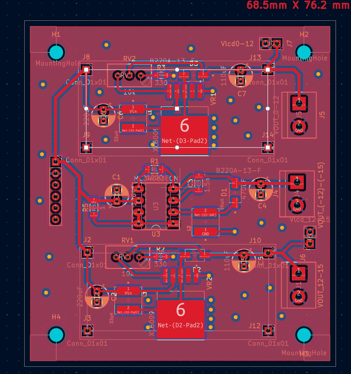
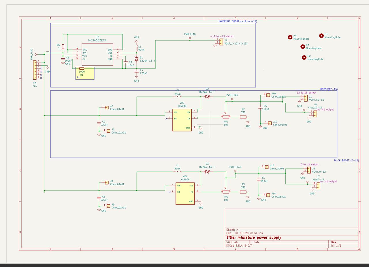
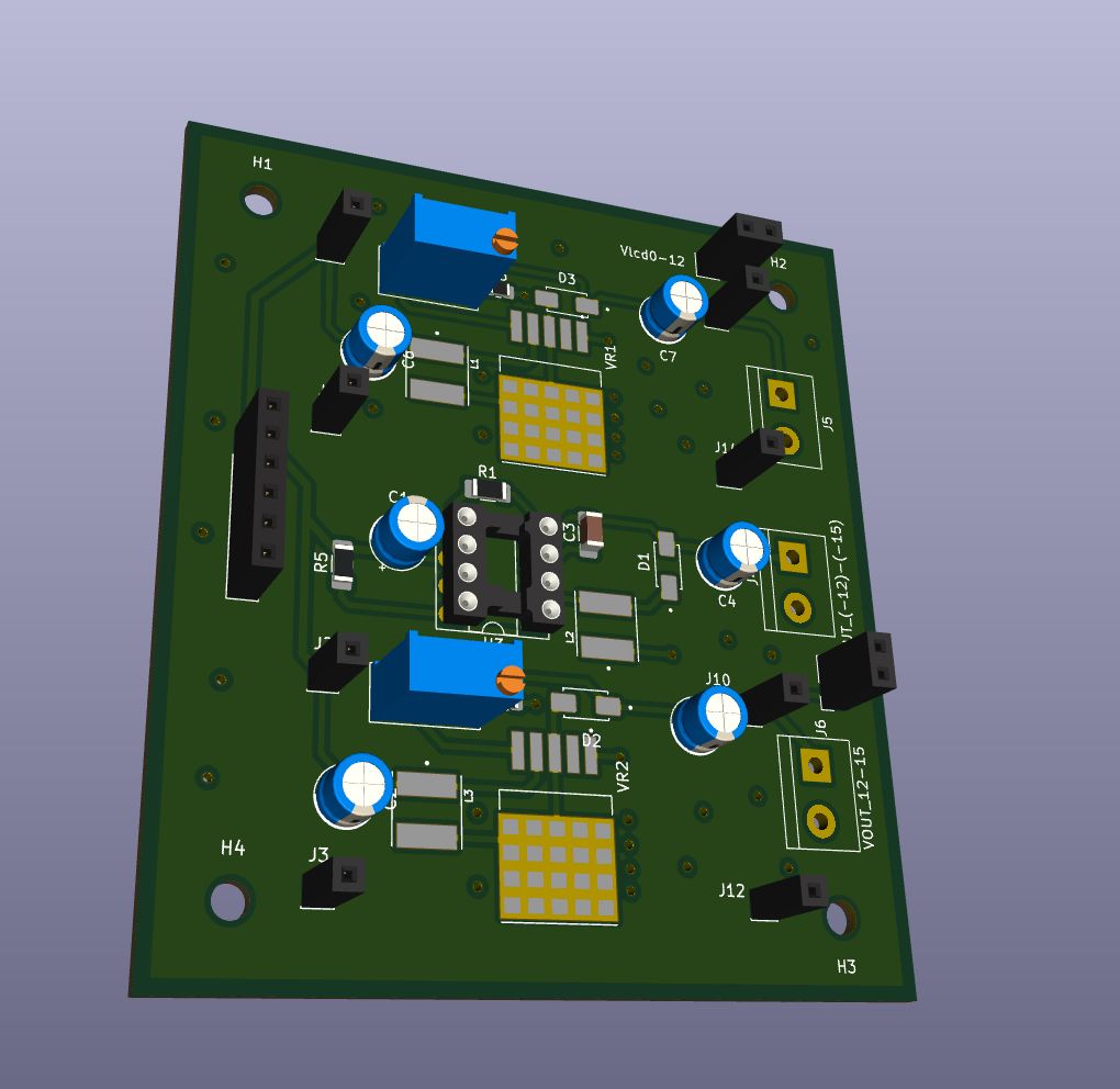
design.kicad_sch (Master Schematic): Contains the logical circuit design, component symbol definitions, and netlists. It details the wiring between the USB-C power delivery network, the switching regulators, the microcontroller interface, and the digital potentiometers used for feedback loop control.design.kicad_pcb (Board Layout): The physical 2D layout of the PCB (1.6mm standard thickness). This file defines component placement, copper trace routing, via stitching, and dedicated ground/power planes required for stable DC-DC conversion.The board is engineered to take standard mobile charger inputs and step them up/down to provide clean, adjustable output voltages for breadboard prototyping.
Input Stage:
Output Stages:
Key Components Implemented:
PCB Design Considerations & Engineering Choices
To ensure reliable operation and clean power delivery, the following design constraints were implemented in the board layout (design.kicad_pcb):
Current Handling & Trace Widths: High-current pathways—specifically from the USB-C input to the inductors and out to the load terminals—are routed with widened traces calculated to safely handle up to 2A of continuous current without excessive temperature rise.
Thermal Management: Extensive copper pours and via stitching are utilized around the MC34063ADG switching regulators to dissipate heat effectively during heavy loads.
Noise Isolation (Signal Integrity): Switching power supplies inherently generate noise. We deliberately separated the high-frequency switching nodes of the DC-DC converters from the sensitive analog ADC feedback traces and the digital SPI communication lines to prevent parasitic coupling and ensure stable output regulation.
Voltage Monitoring: Dedicated ADC feedback paths are routed directly to the microcontroller to allow closed-loop monitoring and real-time adjustment of the output voltages.
Our original system architecture relied heavily on a custom-designed printed circuit board (PCB) to integrate an STM32 microcontroller with a digital potentiometer for software-controlled voltage regulation. We successfully completed the complete schematic and board layout for this design.
The Challenge: During the final submission phase, a miscommunication regarding the final PCB fabrication deadline with a TA resulted in our team missing the manufacturing window. Although our design files were complete, we were unable to obtain the physical custom boards required to mount our microcontroller and surface-mount components.
Attempted Workarounds: Without the custom PCB, utilizing our microcontroller-based digital feedback loop became a significant challenge. Under the guidance of Ankur Sir, we initially attempted to migrate our design to standard breakout boards. However, the complexity of the digital-to-analog routing and the high-frequency switching noise of the power stages made a reliable breadboard/perfboard integration of the STM32 and digital potentiometer unfeasible.
Final Resolution & Direct Implementation: To ensure we delivered a functional power supply that met the core voltage requirements of the problem statement, we executed a hardware pivot. We abandoned the unavailable digital control loop and opted for a direct analog implementation.
We procured standalone buck-boost IC modules and directly implemented them to handle the power conversion. While this meant sacrificing the digital LCD interface and rotary encoder functionality we had programmed, it allowed us to successfully demonstrate the core power-delivery mechanics of the project (stepping a 5V USB input to the required variable output voltages) using a robust, alternative prototype.
| Qty | Value | Footprint | References |
|---|---|---|---|
| 8 | Conn_01x01 | Connector_PinSocket_2.54mm:PinSocket_1x01_P2.54mm_Vertical | J2, J3, J8, J9, J10, J12, J13, J14 |
| 4 | MountingHole | MountingHole:MountingHole_3mm | H1, H2, H3, H4 |
| 1 | 1 | Resistor_SMD:R_1206_3216Metric_Pad1.30x1.75mm_HandSolder | R5 |
| 1 | 1.5nF | Capacitor_SMD:C_1206_3216Metric_Pad1.33x1.80mm_HandSolder | C3 |
| 1 | 1000 | Resistor_SMD:R_1206_3216Metric_Pad1.30x1.75mm_HandSolder | R1 |
| 1 | 100uF | Capacitor_THT:CP_Radial_D5.0mm_P2.50mm | C1 |
| 1 | 470uF | Capacitor_THT:CP_Radial_D5.0mm_P2.50mm | C4 |
| 1 | 90uH | VLS6045EX-6R8M:IND_VLS6045EX-6R8M | L2 |
| 1 | B220A-13-F | B220A-69-F:DIOM5226X230N | D1 |
| 1 | MC34063ECN | Package_DIP:DIP-8_W7.62mm_Socket_LongPads | U3 |
| 1 | VOUT_(-12)-(-15) | TerminalBlock.pretty-master:TerminalBlock_bornier-2_P5.08mm | J4 |
| 1 | VOUT_0-12 | TerminalBlock.pretty-master:TerminalBlock_bornier-2_P5.08mm | J5 |
| 1 | VOUT_12-15 | TerminalBlock.pretty-master:TerminalBlock_bornier-2_P5.08mm | J1 |
| 1 | Vin | Connector_PinSocket_2.54mm:PinSocket_1x06_P2.54mm_Vertical | J11 |
| 1 | Vlcd0-12 | Connector_PinSocket_2.54mm:PinSocket_1x02_P2.54mm_Vertical | J7 |
| 1 | Vlcd_12-15 | Connector_PinSocket_2.54mm:PinSocket_1x02_P2.54mm_Vertical | J6 |
It measures 68.6 × 76.2 mm and has 2 copper layers, 1.6 mm thick.
26 parts, built around the MC34063ECN. The full list of its parts is on this page, with links to each part's symbol and footprint where PCBKit's library has them.
From the dharmandermina88-wq/CPU- repository on GitHub, at the commit this page was made from: the board is pcb/design.kicad_pcb and its schematic pcb/KiCad_Project/EDL_TUE20.kicad_sch. PCBKit opens the board in the browser, with nothing to install.
Its repository states no licence, so its author keeps all rights: ask dharmandermina88-wq before reusing the design.

kami-sona/Kicad_project
This is a is single board PCB layout for PWM_GENERATOR

r4hulrr/ausign
Real-time Auslan (Australian Sign Language) to English speech translation glove. Built with ESP32-S3, flex sensors, IMU on a custom PCB, and a Bluetooth-connected Python GUI.


hackclub/OnBoard
💡 Join 1,000 teenagers and make your first PCB with a $100 grant!


harbaum/galagino
A Galaga, Pac-Man and Donkey Kong arcade emulator for the ESP32