


2 layers77.5 × 100 mm
Rover pdb
devkyber/PCB
AI-assisted PCB engineering for native KiCad: source evidence, scoped changes, checked previews, human review, and reproducible release packages.
93 parts

 devkyber/PCB
AI-assisted PCB engineering for native KiCad: source evidence, scoped changes, checked previews, human review, and reproducible release packages.
Usb c power is an open-source printed circuit board by devkyber, from the devkyber/PCB repository on GitHub. It is a 2-layer board of 60 × 40 mm with 10 parts on 6 nets, routed with 28 tracks and 7 vias.
It is built around the MFR-25FBF52-5K1, HTSW-102-07-G-S and MF-MSMF075-2, with the SMAJ6.0A, USB4125-GF-A and WP710A10ID among its other parts. Its parts include 3 resistors, 2 diodes, 2 connectors and 1 fuse.


An unbuilt educational DRAFT for trying PCB Copilot on a complete, small KiCad design. Four independent 0 to 3.3 V inputs drive four red LEDs through 1.1 kOhm resistors. The 45 x 35 mm board has two copper layers, through-hole components, two mounting holes, project-local libraries and all three package models.
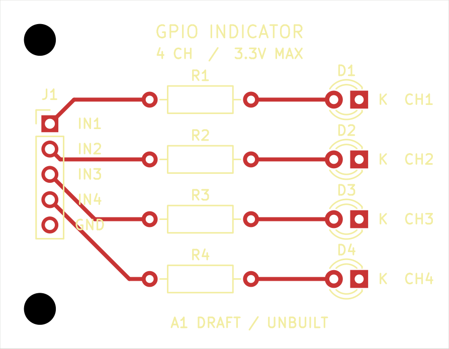
Open gpio-indicator.kicad_pro in KiCad 10, or inspect the schematic PDF, schematic image, assembly drawing, front copper and mirrored underside. The GLB model is a native CAD visualization; it does not establish actual component fit.
From the repository root:
uv run pcb-copilot doctor
uv run pcb-copilot status examples/gpio-indicator
uv run pcb-copilot research examples/gpio-indicator --verify
uv run pcb-copilot research examples/gpio-indicator --verify-schematic-parts
uv run pcb-copilot review examples/gpio-indicator
The last command deliberately returns exit 1: supplier assembly rotation contracts and all five human review decisions are absent. Native ERC and DRC are clean, connectivity and forward-annotation links agree, and the independent dated JLCPCB geometry check passes. These results are scoped machine checks, not fabrication approval or measured performance. See the saved review and author inspection record.
J1 pins 1 through 4 are IN1 through IN4; pin 5 is GND. It has no power pin. With a 3.3 V input and initial 1% resistance tolerance, the calculation gives at most 3.031 mA per channel, taking no credit for LED forward voltage. That loading must suit the actual controller's per-pin and aggregate drive limits. Actual brightness, current, fit, assembly and external-controller behavior remain unqualified.
The resistor was deliberately chosen as 1.1 kOhm: 1 kOhm at its negative 1% tolerance would allow a 3.333 mA zero-Vf bound. The requirements and design basis state the assumptions and scope. This example has no ESD protection, isolation, level conversion, voltage regulation or approval for an application.
Exact manufacturer PDF bytes are in evidence. The library receipt binds official KiCad footprint copies, pad functions, manufacturer evidence and local model bytes to their hashes. The local footprint files change only model URIs. Board instances use wider silkscreen strokes to meet the workspace baseline; numbered pad geometry is unchanged. Generic package models are visualization aids.
The saved native CAD is authoritative. A construction script must not overwrite later edits. Use a separate copy for experiments and the shared candidate workflow for checked updates. No owner board or frozen test fixture was modified to create this example.
| Qty | Value | Footprint | References |
|---|---|---|---|
| 3 | 5.1 kOhm 1% | USBC:R_Axial_DIN0207_L6.3mm_D2.5mm_P10.16mm_Horizontal | R1, R2, R3 |
| 2 | M3 NPTH | USBC:MountingHole_3.2mm_M3 | H1, H2 |
| 1 | Fused 5 V OUT | USBC:PinHeader_1x02_P2.54mm_Vertical | J2 |
| 1 | PPTC 0.75 A | BournsDerived:MF-MSMF075_1812_Style1 | F1 |
| 1 | SMAJ6.0A | USBC:D_SMA | D1 |
| 1 | USB4125-GF-A | USBC:USB_C_Receptacle_GCT_USB4125-xx-x_6P_TopMnt_Horizontal | J1 |
| 1 | WP710A10ID | USBC:LED_D3.0mm | D2 |
It measures 60 × 40 mm and has 2 copper layers, 1.6 mm thick.
10 parts, built around the MFR-25FBF52-5K1, HTSW-102-07-G-S, MF-MSMF075-2 and SMAJ6.0A. The full list of its parts is on this page, with links to each part's symbol and footprint where PCBKit's library has them.
From the devkyber/PCB repository on GitHub, at the commit this page was made from: the board is examples/usb-c-power/usb-c-power.kicad_pcb and its schematic examples/gpio-indicator/gpio-indicator.kicad_sch. PCBKit opens the board in the browser, with nothing to install.
Its repository states no licence, so its author keeps all rights: ask devkyber before reusing the design.
devkyber/PCB
AI-assisted PCB engineering for native KiCad: source evidence, scoped changes, checked previews, human review, and reproducible release packages.

devkyber/PCB
AI-assisted PCB engineering for native KiCad: source evidence, scoped changes, checked previews, human review, and reproducible release packages.

devkyber/PCB
AI-assisted PCB engineering for native KiCad: source evidence, scoped changes, checked previews, human review, and reproducible release packages.

devkyber/PCB
AI-assisted PCB engineering for native KiCad: source evidence, scoped changes, checked previews, human review, and reproducible release packages.


cminyard/PacSatBaseBoard
Base board outline and connectors for PacSat boards

jodhsinghnahal/piezo_matlab
Simulation, circuit and PCB design repository for investigating piezoelectric energy harvesting (PEH) interfaces under conventional vibration excitation and underwater acoustic excitation.

8aChristian/InduLink-485
The board follows rigorous IPC (IPC-2152, IPC-2221, IPC-7351) standards, complete with galvanic isolation, industrial transient protection (TVS, Schottky, PTC Polyfuse), a wide-input step-down switching power…


suvi2005/ece445
digit: will hold anything related to the project: pcb, code, designs etc. lab-notebook: (self-explanatory)

sabas0ba/kicad_skills
Container-based toolkit for circuit design: datasheets, SPICE simulation and KiCad review