4 layers96.5 × 132.7 mm

 devisunofficial/MoonDeck
MoonDeck is a Desk gadget which has three purposes, I display to display whatever I want, a magnetic charger to charge my phone (wirelessly), and a mic to listen commands.
MoonDeck is an open-source printed circuit board by devisunofficial, from the devisunofficial/MoonDeck repository on GitHub. It is a 2-layer board of 61.8 × 42.8 mm with 44 parts on 41 nets, routed with 328 tracks and 52 vias.
It is built around the MP2315SGJ-Z, MBR0530 and DC-005-5A-2.0-SMT, with the FPC-05F-24PH20 among its other parts. Its parts include 16 capacitors, 9 resistors, 3 ICs, 3 diodes and 2 inductors. It belongs with the ESP32 boards of this library.


MoonDeck is a Desk gadget which has three purposes, I display to display whatever I want, a magnetic charger to charge my phone (wirelessly), and a mic to listen commands.
It uses a E-ink display so that distraction is minimal and doesn't stress eyes. It charges as 15W because I think 15W is enough, as I can charge my phone overnight.
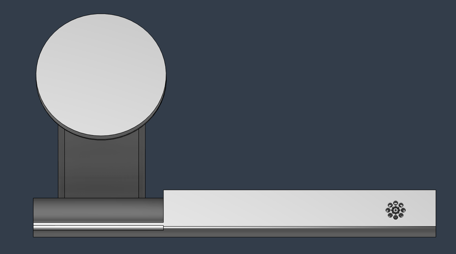 Made in Fusion 360 with love!
3D model will be here once it is completed
Here's my PCB! It was made in KiCad.
Schematic : 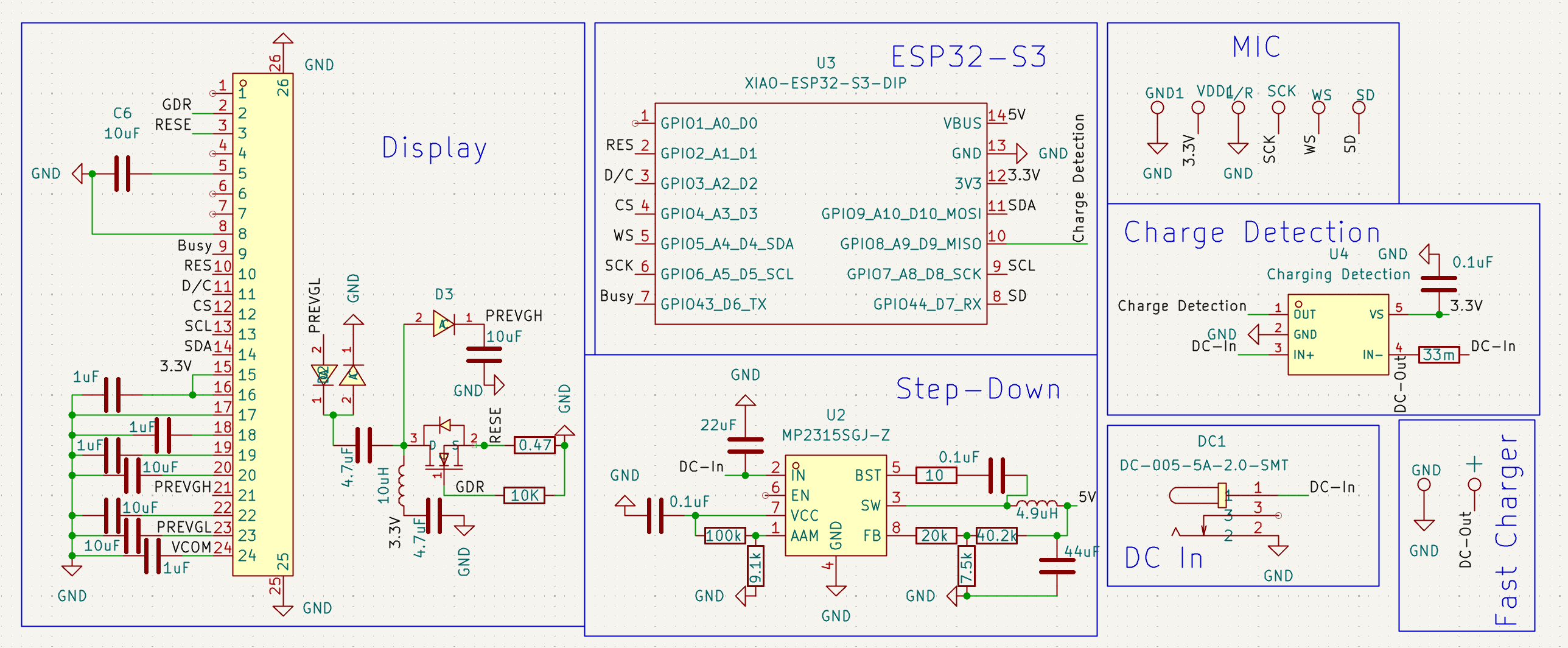 PCB Footprint :
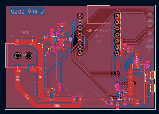
For now it is going to use TRMNL opensource firmware, whose server will be established on my android phone using TERMUX. But it is not the final version. The Final Version will have
I might add more in the future! That's it for now.
| S. No. | Name | Use | Quantity | Cost(USD) |
|---|---|---|---|---|
| 1 | PCB | Main Circuit | 1 | 68 |
| 2 | XIAO ESP 32 | Microcontroller | 1 | 9.44 |
| 3 | 5.83" E-ink Display | Display | 1 | 50 |
| 4 | Magnetic Stand | For Magnets | 1 | 2.5 |
| 5 | Charging Coil | Wireless Charger | 1 | 3.2 |
| 6 | MIC | For Voice Input | 1 | 1.53 |
| 7 | DC Adaptor | Main PoweSource | 1 | 4.5 |
| 8 | Charging Module | To Charge | 1 | 2.5 |
Nothing For Now
| Qty | Value | Footprint | References |
|---|---|---|---|
| 5 | 10uF | Capacitor_SMD:C_0603_1608Metric | C6, C10, C11, C12, C15 |
| 4 | 1uF | Capacitor_SMD:C_0603_1608Metric | C7, C8, C9, C13 |
| 3 | 0.1uF | Capacitor_SMD:C_0603_1608Metric | C1, C3, C4 |
| 3 | MBR0530 | lcsc_footprints:C77336_SOD-123_L2_8-W1_8-LS3_7-RD | D1, D2, D3 |
| 2 | 4.7uF | Capacitor_SMD:C_0603_1608Metric | C14, C16 |
| 2 | TestPoint | Connector_Wire:SolderWirePad_1x01_SMD_1x2mm | GND1, VDD1 |
| 1 | + | Connector_Wire:SolderWirePad_1x01_SMD_1x2mm | TP8 |
| 1 | 0.47 | Resistor_SMD:R_0603_1608Metric | R9 |
| 1 | 10 | Resistor_SMD:R_0603_1608Metric | R4 |
| 1 | 100k | Resistor_SMD:R_0603_1608Metric | R2 |
| 1 | 10K | Resistor_SMD:R_0603_1608Metric | R8 |
| 1 | 10uH | Inductor_SMD:L_0805_2012Metric | L2 |
| 1 | 20k | Resistor_SMD:R_0603_1608Metric | R5 |
| 1 | 22uF | Capacitor_SMD:C_0603_1608Metric | C2 |
| 1 | 33m | Resistor_SMD:R_0603_1608Metric | R1 |
| 1 | 4.9uH | Inductor_SMD:L_0805_2012Metric | L1 |
| 1 | 40.2k | Resistor_SMD:R_0603_1608Metric | R7 |
| 1 | 44uF | Capacitor_SMD:C_0805_2012Metric | C5 |
| 1 | 7.5k | Resistor_SMD:R_0603_1608Metric | R6 |
| 1 | 9.1k | Resistor_SMD:R_0603_1608Metric | R3 |
| 1 | Charging Detection | lcsc_footprints:C116203_SOT-23-5_L3_0-W1_7-P0_95-LS2_8-BR | U4 |
| 1 | DC-005-5A-2.0-SMT | EasyEDA:DC-IN-TH_DC-005-5A-2.0-SMT | DC1 |
| 1 | FPC-05F-24PH20 | EasyEDA:FPC-SMD_24P-P0.50_FPC-05F-24PH20 | FPC1 |
| 1 | GND | Connector_Wire:SolderWirePad_1x01_SMD_1x2mm | TP7 |
| 1 | L/R | Connector_Wire:SolderWirePad_1x01_SMD_1x2mm | TP3 |
| 1 | MP2315SGJ-Z | EasyEDA:TSOT-23-8_L2.9-W1.6-P0.65-LS2.8-BL | U2 |
| 1 | SCK | Connector_Wire:SolderWirePad_1x01_SMD_1x2mm | TP4 |
| 1 | SD | Connector_Wire:SolderWirePad_1x01_SMD_1x2mm | TP6 |
| 1 | SI1304BDL_C7419947 | lcsc_footprints:C7419947_SOT-323-3_L2_0-W1_3-P1_30-LS2_1-BL | Q1 |
| 1 | WS | Connector_Wire:SolderWirePad_1x01_SMD_1x2mm | TP5 |
| 1 | XIAO-ESP32-S3-DIP | Seeed Studio XIAO Series Library:XIAO-Generic-Thruhole-14P-2.54-21X17.8MM | U3 |
It measures 61.8 × 42.8 mm and has 2 copper layers, 1.6 mm thick.
44 parts, built around the MP2315SGJ-Z, MBR0530, DC-005-5A-2.0-SMT and FPC-05F-24PH20. The full list of its parts is on this page, with links to each part's symbol and footprint where PCBKit's library has them.
From the devisunofficial/MoonDeck repository on GitHub, at the commit this page was made from: the board is Moondeck/Moondeck.kicad_pcb and its schematic Moondeck/Moondeck.kicad_sch. PCBKit opens the board in the browser, with nothing to install.
Its repository states no licence, so its author keeps all rights: ask devisunofficial before reusing the design.

swayerloren/KICAD_ENGINE
AI-assisted KiCad PCB design workflow for schematics, PCB layouts, DRC, BOM/CPL, and fabrication outputs using Codex or Claude.


BaoneBosima/4_Channel_DC_Motor_Driver
The board was designed in KiCad 8.0 utilizing a 4-layer, impedance-controlled stackup to ensure signal integrity in a mixed-signal environment.

INTenX/test-controller-carrier-esp32
Carrier Board for ESP32-S3-DevKitC-1 that includes a 4 channel DAC and 8 channel ADC external expansion, as well power routing / monitoring.
