Skip to the content
PCBKitNew board
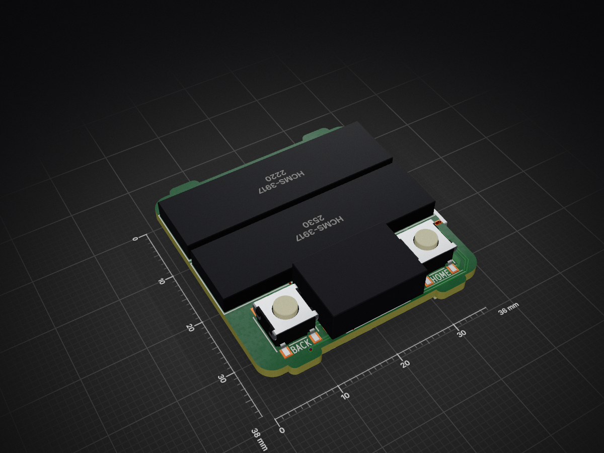
2 layers36 × 38 mmDigicron, the printed circuit board in 3D

Software and hardware for the DigiCron smartwatch.

Size
36 × 38 mm
Copper layers
2
Thickness
1.6 mm
Parts
56
Nets
94
Pads
257
Tracks, vias
1,123, 92
Pours
4
Routed
Yes
KiCad
KiCad 9.0 (file 20241229)
Created
6 Sep 2024
Updated
23 Jan 2026

Overview

Digicron is an open-source printed circuit board by devicefuture, from the devicefuture/digicron repository on GitHub, published under the MIT licence. It is a 2-layer board of 36 × 38 mm with 56 parts on 94 nets, routed with 1,123 tracks and 92 vias.

It is built around the MDBT50Q-U1MV2, BME280 and HCMS-3917, with the ADXL345BCCZ-RL, RT9080-33GJ5 and 12401598E4#2A among its other parts. Its parts include 18 resistors, 9 connectors, 8 capacitors, 8 ICs and 4 diodes. It belongs with the nRF52 and nRF5x boards of this library.

Main components

12

README

README.md

DigiCron

Software and hardware for the DigiCron smartwatch.

Want to try out the DigiCron's firmware in your browser? Just visit the DigiCron Simulator!

Getting the code

You must clone this repo like this:

bash
git clone --recurse-submodules https://github.com/devicefuture/digicron

--recurse-submodules must be used because this repo contains Git submodules which are used as libraries for the firmware and simulator.

Building

Before building the firmware for the first time, you will need to install the development dependencies:

bash
./build.sh --install-dev

To build the firmware and upload it to the target device over USB, run:

bash
./build.sh --upload

You can also check for compilation errors without uploading by removing the --upload flag.

To build the firmware and the simulator, run:

bash
./build.sh --sim

Then to run the simulator locally, you need to start a web server in this directory. You can run the following to start the web server at localhost:8000:

bash
python3 -m http.server

Parts

56
QtyValueFootprintReferences
5100KResistor_SMD:R_0402_1005Metric_Pad0.72x0.64mm_HandSolderR202, R203, R205, R206, R207
410KResistor_SMD:R_0402_1005Metric_Pad0.72x0.64mm_HandSolderR102, R104, R106, R107
4Solder padConnector_Wire:SolderWirePad_1x01_SMD_1x2mmJ100, J101, J102, J103
4Solder padTestPoint:TestPoint_Pad_2.0x2.0mmJ201, J202, J203, J204
310uCapacitor_SMD:C_0402_1005Metric_Pad0.74x0.62mm_HandSolderC200, C201, C205
322uCapacitor_SMD:C_0402_1005Metric_Pad0.74x0.62mm_HandSolderC202, C203, C204
2100Resistor_SMD:R_0402_1005Metric_Pad0.72x0.64mm_HandSolderR101, R103
222Resistor_SMD:R_0402_1005Metric_Pad0.72x0.64mm_HandSolderR209, R210
225pCapacitor_SMD:C_0402_1005Metric_Pad0.74x0.62mm_HandSolderC206, C207
25.1KResistor_SMD:R_0402_1005Metric_Pad0.72x0.64mm_HandSolderR200, R201
2HCMS-3917HCMS-x91x:DIP26_HCMS-290X-B_BRAU101, U102
2SW_Push_DualSMD_SW_6mm:SW_Push_1P1T_NO_6x6mm_H9.5mmSW200, SW201
112401598E4#2AUSB-C:12401598E4#2AX200
114Resistor_SMD:R_0402_1005Metric_Pad0.72x0.64mm_HandSolderR100
11N4148WDiode_SMD:D_SOD-123D101
11uInductor_SMD:L_1008_2520Metric_Pad1.43x2.20mm_HandSolderL200
14.7KResistor_SMD:R_0402_1005Metric_Pad0.72x0.64mm_HandSolderR208
1732KResistor_SMD:R_0402_1005Metric_Pad0.72x0.64mm_HandSolderR204
1ADXL345BCCZ-RLADXL345:LGA_CC-14-1_ADIU104
1AO3400APackage_TO_SOT_SMD:SOT-23Q101
1AO3401AAO3401A:SOT-23-3L_AOSQ200
1BAT54CWPackage_TO_SOT_SMD:SOT-323_SC-70D201
1BME280Package_LGA:Bosch_LGA-8_2.5x2.5mm_P0.65mm_ClockwisePinNumberingU105
1BSS138Package_TO_SOT_SMD:SOT-23Q100
1Conn_Receptacle_2PConnector_Molex:Molex_PicoBlade_53261-0271_1x02-1MP_P1.25mm_HorizontalJ200
1ECX-.327-CDX-1293ECX-.327-CDX-1293:XTAL_ECS-.327-12.5-34RR-TRXTAL200
1IR LEDLED_THT:LED_D5.0mm_Horizontal_O1.27mm_Z3.0mm_IRBlackD100
1MBR0540Diode_SMD:D_SOD-123D200
1MCP73831-2-OTPackage_TO_SOT_SMD:SOT-23-5U202
1MDBT50Q-U1MV2RF_Module:Raytac_MDBT50QU100
1MU-AS90RMU-AS90R:MU-AS90RSW202
1RT9080-33GJ5RT9080:TSOT-23-5_RITU200
1TPS61023DRLRTPS61023:DRL0006AU201

Questions

How big is the Digicron PCB?

It measures 36 × 38 mm and has 2 copper layers, 1.6 mm thick.

What parts does the Digicron use?

56 parts, built around the MDBT50Q-U1MV2, BME280, HCMS-3917 and ADXL345BCCZ-RL. The full list of its parts is on this page, with links to each part's symbol and footprint where PCBKit's library has them.

Where can I download the Digicron KiCad files?

From the devicefuture/digicron repository on GitHub, at the commit this page was made from: the board is hardware/DigiCron.kicad_pcb and its schematic hardware/DigiCron.kicad_sch. PCBKit opens the board in the browser, with nothing to install.

Can I use the Digicron design in my own project?

Its repository publishes it under the MIT licence: you may reuse it on that licence's terms (keep the author's notice, and for a copyleft licence share your changes alike).

Similar boards

  • 4 layersDial me spinner main, the printed circuit board in 3D

    Dial me spinner main

    tyevco/dial-me-spinner

    A Bluetooth dial spinner about 70 mm across, built on the nRF52840. A heavy, balanced stainless flywheel ring spins around a stationary centre that holds a colour OLED and a ring of 48 addressable RGB LEDs.

    209 parts
  • 4 layers115.9 × 51.1 mmXbx nrf, the printed circuit board in 3D

    Xbx nrf

    zuidec/xbx-nrf

    A replacement bottom board for the Xbox Series X|S controller (model 1914) built on a Nordic nRF52840, with a 2.4 GHz USB dongle instead of Xbox Wireless / Bluetooth
    91 parts
  • 4 layers138.1 × 104.6 mmV7-kaleido, the printed circuit board in 3D

    V7-kaleido

    vroland/epdiy-hardware

    Hardware design files for EPDiy: https://github.com/vroland/epdiy.

    140 parts75CC-BY-SA-4.0
  • 4 layers98 × 75 mmPiFinder4, the printed circuit board in 3D

    PiFinder4

    brickbots/PiFinder

    A plate solving telescope finder based around a Raspberry PI and RPI HQ Camera

    157 parts257GPL-3.0
  • 4 layers47.1 × 33.5 mmGamePad I2S audio, the printed circuit board in 3D

    GamePad I2S audio

    intergalaktik/Extension_Boards_for_Olimex_GateMate

    Simple extension boards for Olimex GateMate FPGA Board

    85 parts20
  • 4 layers46.8 × 52.4 mmVORTAC, the printed circuit board in 3D

    VORTAC

    FoCTow/ToolchangerDevelopment

    Overcomplicated 3D Printer Design

    146 parts2
  • 4 layers81.1 × 85 mmSTS1 EDU V3 0, the printed circuit board in 3D

    STS1 EDU V3 0

    SpaceTeam/STS1_EDU_Hardware

    Contains all Hardware Informations from EDU 2.6 onwards

    108 parts2
  • 2 layers22 × 39 mmPhilly Node, the printed circuit board in 3D

    Philly Node

    tasmaniandroid/Philly_Node

    The start of a Philly-Centric mesh node.

    77 parts2CERN-OHL-S-2.0