
2 layers178 × 145 mm
Ultra DB X51 v1
ExploreEmbedded/8051_DevelopmentBoard
Design files and sample code for 8051 development Ultra Boards
145 parts70
 devanmehta/Bluetooth-Receiver
A Bluetooth audio receiver built on an ESP32-WROOM-32D in ESP-IDF C++. The system receives stereo audio from a phone over Bluetooth Classic, outputs the decoded audio through PCM5102A DAC, and displays the current song…
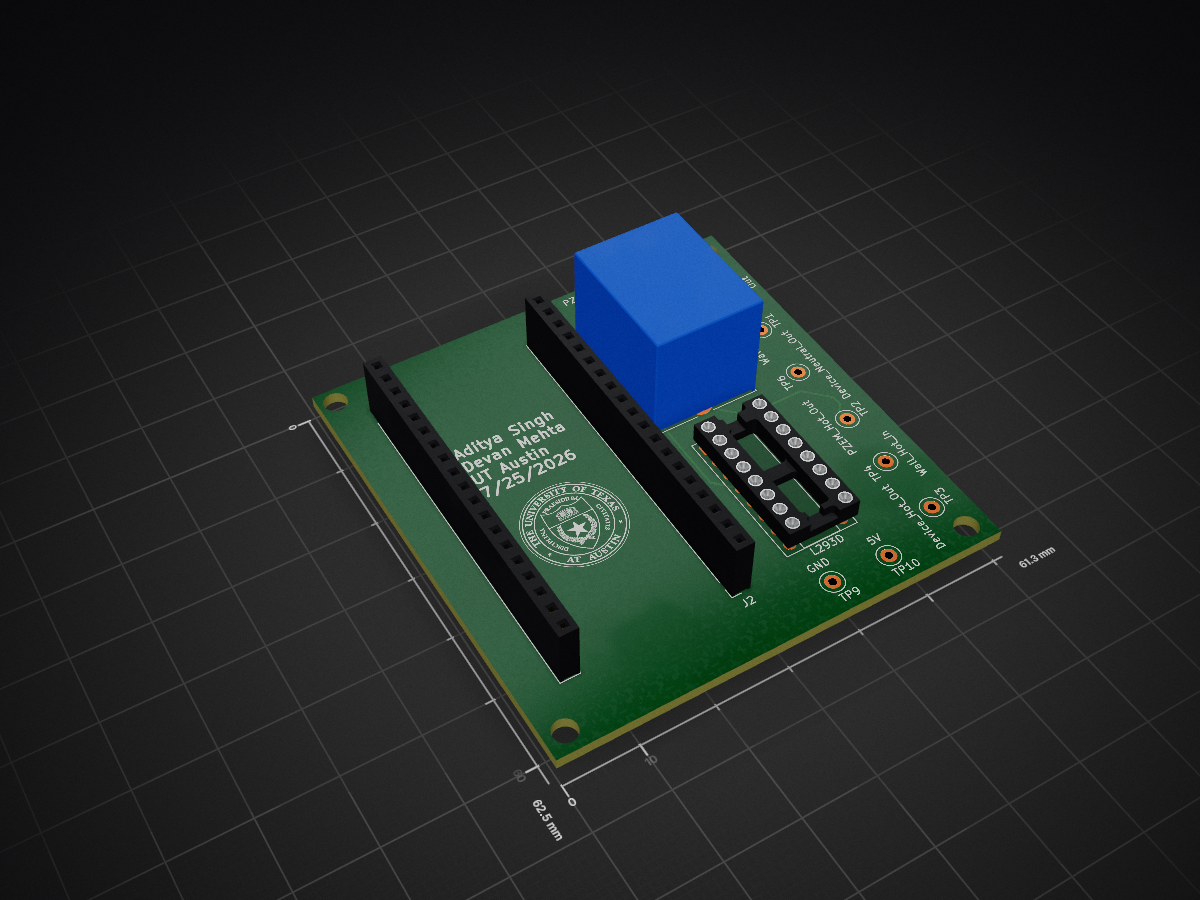
EnergyOptPCB is an open-source printed circuit board by devanmehta, from the devanmehta/Bluetooth-Receiver repository on GitHub. It is a 2-layer board of 61.3 × 62.5 mm with 15 parts on 52 nets, routed with 54 tracks and 0 vias.
It is built around the L293D. Its parts include 2 connectors, 1 IC and 1 switch.
A Bluetooth audio receiver built on an ESP32-WROOM-32D in ESP-IDF C++. The system receives stereo audio from a phone over Bluetooth Classic, outputs the decoded audio through PCM5102A DAC, and displays the current song, artist, album, and playback status to an LCD Display in real time, all housed in a custom PCB.
| Item | Estimated cost (USD) |
|---|---|
| ESP32-WROOM-32D development board | $6–$10 |
| 1.8-inch ST7735R TFT module | $5–$20 |
| PCM5102A I2S DAC module | $5–$10 |
| Headers, connectors, and miscellaneous hardware | $2–$5 |
| USB cable and power source, if needed | $3–$8 |
| (Optional) two-layer PCB, allocated per board from a small order | $4–$10 |
| Estimated total | $25–$63 |
IMPORTANT: This project requires an ESP32 variant with Bluetooth Classic support. A2DP and AVRCP cannot run on ESP32 variants that provide only Bluetooth Low Energy (BLE).
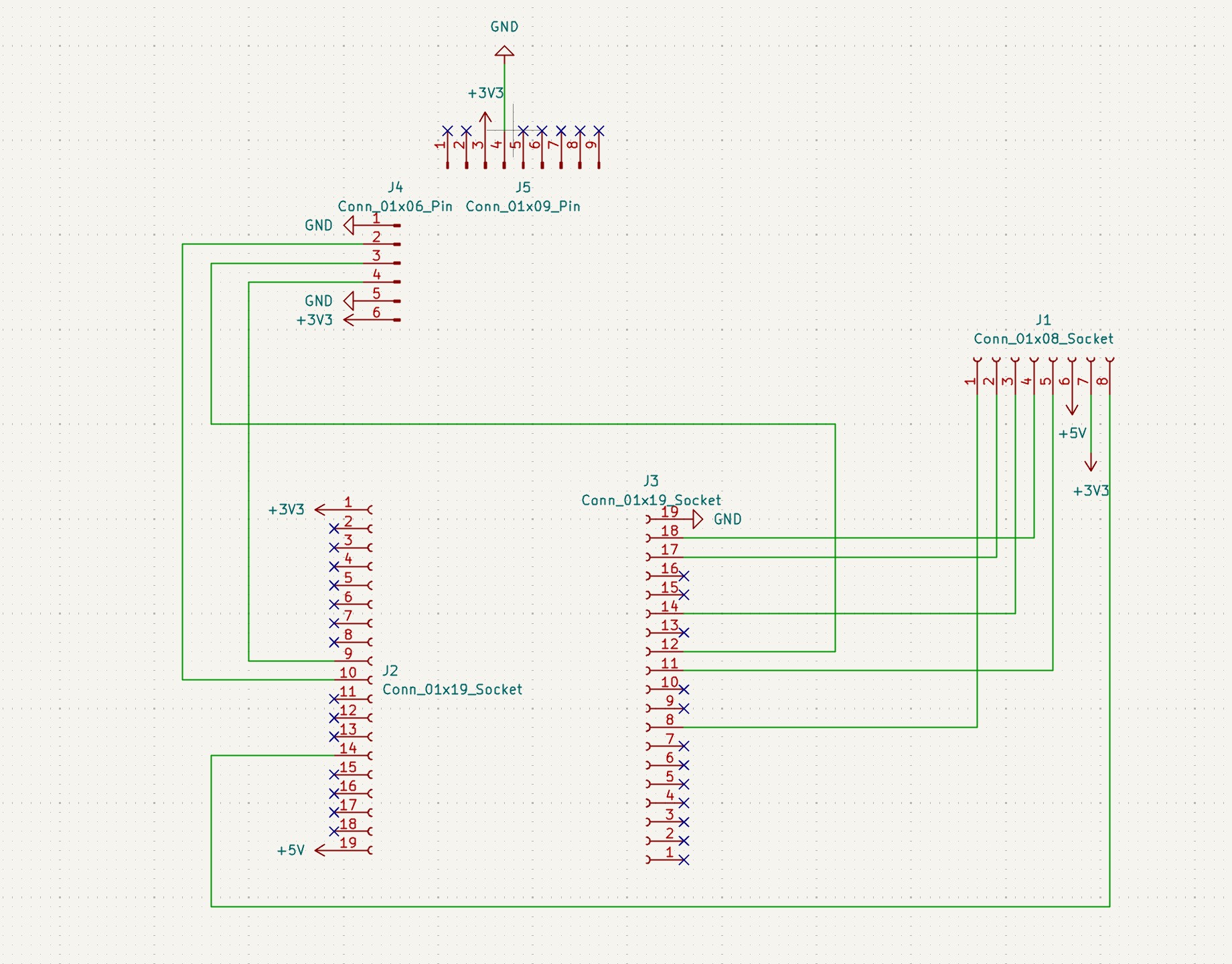
| PCM5102A signal | ESP32-WROOM-32D GPIO | Purpose |
|---|---|---|
| BCK | GPIO 26 | I2S bit clock generated by the ESP32 |
| LCK / LRCK / WS | GPIO 25 | Left/right word-select clock |
| DIN | GPIO 19 | PCM audio data from the ESP32 to the DAC |
| MCLK / SCK | Not connected | The current configuration does not require an ESP32 MCLK output |
| GND | GND | Shared electrical reference |
| ST7735R signal | ESP32-WROOM-32D GPIO | Purpose |
|---|---|---|
| SCL / SCLK | GPIO 18 | SPI clock |
| SDA / MOSI / DIN | GPIO 23 | SPI data from the ESP32 to the display |
| DC / A0 | GPIO 21 | Selects display data or commands |
| CS | GPIO 22 | Display chip select |
| RST / RESET | GPIO 16 | Display hardware reset |
| MISO | Not connected | The application only writes to the display |
| GND | GND | Shared electrical reference |
| Signal | ESP32-WROOM-32D GPIO | Purpose |
|---|---|---|
| Onboard LED | GPIO 2 | Indicates Bluetooth connection status |
KiCad source lives in the Hardware/
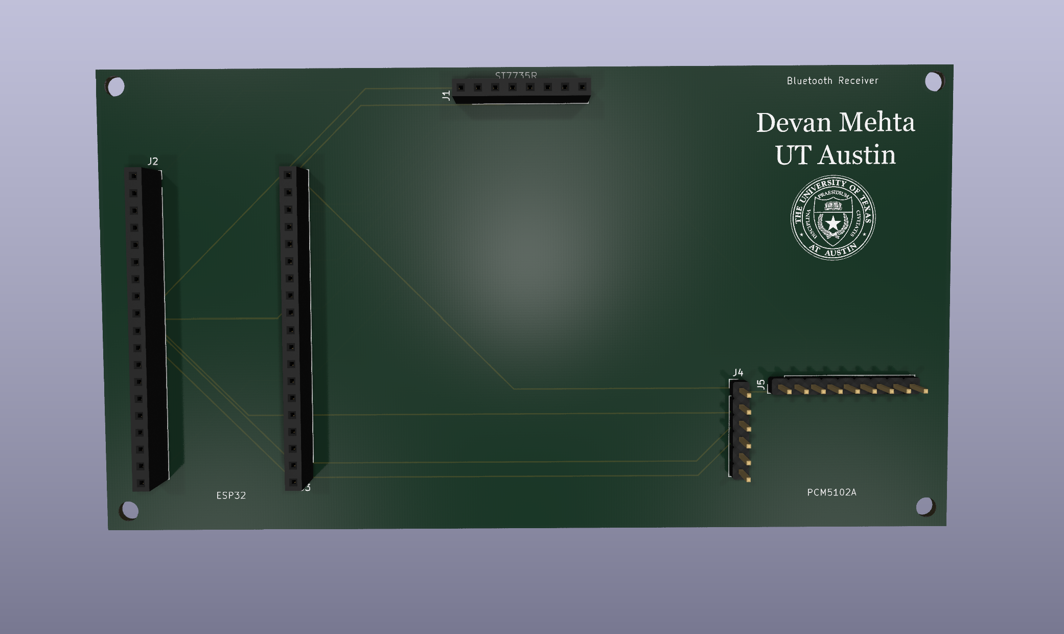
PCB Top |
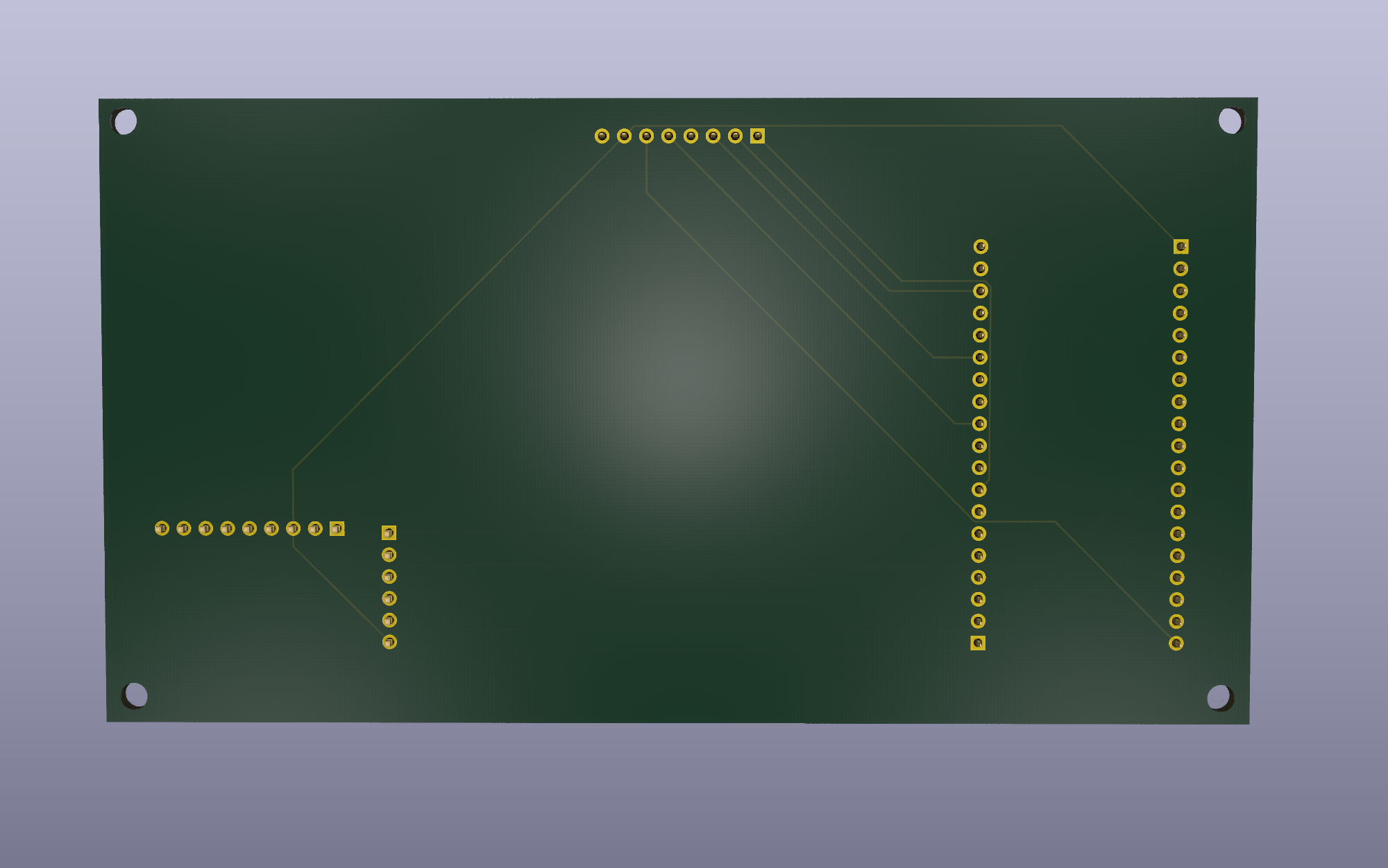
PCB Bottom |
Requirements:
The repository includes platformio.ini, ESP-IDF CMake files, and board-specific SDK configuration files. PlatformIO uses them to select the framework, board environment, dependencies, and required ESP-IDF features.
git clone <this-repo-url>
cd <project-folder>
pio run --target upload
pio device monitor
Once flashed, the board advertises itself over Bluetooth as "BT Audio" — pair your phone and start playing music.
├── Hardware/              # KiCad PCB and Design files
├── lib/                   # Project-local libraries, if used
├── src/
│   ├── CMakeLists.txt     # ESP-IDF component registration
│   └── main.cpp           # Main Firmware
├── test/
├── .gitignore
├── CMakeLists.txt
├── platformio.ini         # PlatformIO environment and dependencies
├── sdkconfig.esp32dev     # ESP-IDF board configuration
└── README.mdSeveral pieces of the program can run independently:
| Execution context | Created by | Work performed |
|---|---|---|
| Main application task | ESP-IDF | Initialization and deferred TFT updates |
| Bluedroid Bluetooth task | ESP-IDF Bluetooth stack | Invokes the A2DP and AVRCP callbacks |
| Bluetooth status LED task | Application | Controls the onboard LED from connection state |
The firmware explicitly creates the LED task with xTaskCreate(). Bluetooth tasks are created internally when the controller and Bluedroid stack are enabled.
Our LGFX class inherits from lgfx::LGFX_Device and owns the panel and SPI bus objects:
lgfx::Panel_ST7735S _panel_instance;
lgfx::Bus_SPI       _bus_instance;
The bus configuration selects SPI2_HOST, SPI mode 0, and a 20 MHz write clock. MISO is disabled because the application does not read data from the TFT.
The panel configuration defines the chip-select and reset pins, 128 × 160 drawing area, panel offsets, display inversion, and RGB order. The SPI bus is attached to the panel, and the panel is attached to the parent LovyanGFX device. The resulting global lcd object performs all drawing operations.
setup_i2s() creates a transmit-only channel:
i2s_chan_config_t chan_cfg =
    I2S_CHANNEL_DEFAULT_CONFIG(I2S_NUM_AUTO, I2S_ROLE_MASTER);
The ESP32 acts as I2S master and generates the clocks for the PCM5102A. The standard-mode configuration selects:
i2s_channel_init_std_mode() applies the format and pins. i2s_channel_enable() starts the peripheral.
app_main() initializes NVS before Bluetooth because ESP-IDF's Bluetooth stack depends on non-volatile storage. If NVS has an incompatible version or no free pages, the firmware erases that partition and retries initialization.
The application then:
BT Audio.A2DP carries the stereo Bluetooth stream from the source to the ESP32. After Bluedroid decodes a chunk of audio into PCM samples data buffer, it invokes bt_audio_data_callback which writes the audio samples to the DAC with i2s_channel_write
AVRCP provides information about the media session. The callback receives an event identifier and a union containing the corresponding event data.
| AVRCP event | Firmware response |
|---|---|
| Connection-state event | Raises the is_connected flag and requests metadata and playback status using the attr_mask and subscribes to get notified when play status or track changes |
| Metadata-response event | Copies title, artist, or album into our UI arrays` |
| Play-status response | Stores playing, paused, or stopped state and puts into our UI arrays |
| Change-notification event | Requests new track data or updates playback state |
Title, artist, and album commonly arrive as separate AVRCP events. Drawing immediately for every event would cause multiple rapid full-screen redraws. Instead, the callback updates the appropriate buffer and raises need_screen_update
The main loop checks the flag every 50 ms. When an update is pending, it clears the flag and calls update_screen(). This groups closely timed metadata events and reduces visible flicker.
update_screen() opens one LovyanGFX write transaction, clears the screen, and renders the playback indicator, song title, artist, album, labels, and divider.
Made BluetoothStatusLED() as a separate FreeRTOS task that has a 2,048-byte stack and priority 1 (low priority) which uses the is_connected flag (gets updated in bt_avrc_ct_callback) to update LED:
| Bluetooth state | Onboard LED behavior |
|---|---|
| Connected | Continuously on |
| Disconnected | Blinks (700 ms off, then 700 ms on) |
vTaskDelay() blocks the task between transitions instead of consuming CPU time in a busy-wait loop.
After initialization, app_main() remains alive as the UI service loop that polls need_screen_update and updates the screen
| Qty | Value | Footprint | References |
|---|---|---|---|
| 2 | Conn_01x19_Socket | Connector_PinSocket_2.54mm:PinSocket_1x19_P2.54mm_Vertical | J1, J2 |
| 1 | 5V | TestPoint:TestPoint_Loop_D1.80mm_Drill1.0mm_Beaded | TP10 |
| 1 | Device_Hot_Out | TestPoint:TestPoint_Loop_D1.80mm_Drill1.0mm_Beaded | TP3 |
| 1 | Device_Neutral_Out | TestPoint:TestPoint_Loop_D1.80mm_Drill1.0mm_Beaded | TP6 |
| 1 | GND | TestPoint:TestPoint_Loop_D1.80mm_Drill1.0mm_Beaded | TP9 |
| 1 | L293D | Package_DIP:DIP-16_W7.62mm_Socket | U1 |
| 1 | LOGO | UTimage:convertedUTimage | G*** |
| 1 | PZEM_Hot_Out | TestPoint:TestPoint_Loop_D1.80mm_Drill1.0mm_Beaded | TP2 |
| 1 | PZEM_Neutral | TestPoint:TestPoint_Loop_D1.80mm_Drill1.0mm_Beaded | TP5 |
| 1 | PZEM_RX | TestPoint:TestPoint_Loop_D1.80mm_Drill1.0mm_Beaded | TP7 |
| 1 | PZEM_TX | TestPoint:TestPoint_Loop_D1.80mm_Drill1.0mm_Beaded | TP8 |
| 1 | Wall_Hot_In | TestPoint:TestPoint_Loop_D1.80mm_Drill1.0mm_Beaded | TP4 |
| 1 | Wall_Neutral_In | TestPoint:TestPoint_Loop_D1.80mm_Drill1.0mm_Beaded | TP1 |
| 1 | ~ | Relay_THT:Relay_SPDT_SANYOU_SRD_Series_Form_C | K1 |
It measures 61.3 × 62.5 mm and has 2 copper layers, 1.6 mm thick.
15 parts, built around the L293D. The full list of its parts is on this page, with links to each part's symbol and footprint where PCBKit's library has them.
From the devanmehta/Bluetooth-Receiver repository on GitHub, at the commit this page was made from: the board is Hardware/EnergyOptPCB.kicad_pcb and its schematic Hardware/EnergyOptPCB.kicad_sch. PCBKit opens the board in the browser, with nothing to install.
Its repository states no licence, so its author keeps all rights: ask devanmehta before reusing the design.
ExploreEmbedded/8051_DevelopmentBoard
Design files and sample code for 8051 development Ultra Boards

NikodemBartnik/Small-Projects
All of smaller projects (Arduino, PCBs, electronics, code)

geno543/Redropi_highway
the project aims to detect asteroids and meteor movement using high-quality cameras and radar detection methods using an AI model for accurate analysis, and it classifies bodies be in three categories: non-meteor…


harrislab-brown/DropGen
DropGen uses a fluid reservoir and a piezoelectric buzzer to precisely and repeatably dispense small droplets on demand.


