
2 layers61 × 85 mm
 devaexe00/Projects
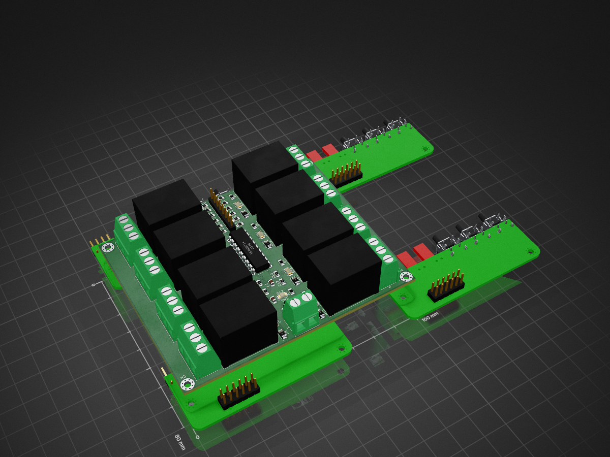
Relaymodule is an open-source printed circuit board by devaexe00, from the devaexe00/Projects repository on GitHub. It is a 2-layer board of 100 × 80 mm with 68 parts on 68 nets, routed with 473 tracks and 48 vias.
It is built around the ULN2803A. Its parts include 25 resistors, 17 diodes, 10 connectors, 9 switches and 2 capacitors.
| Qty | Value | Footprint | References |
|---|---|---|---|
| 16 | 10k | Resistor_SMD:R_0805_2012Metric_Pad1.20x1.40mm_HandSolder | R10, R11, R12, R13, R14, R15, R16, R17, R18, R19, R20, R21, R22, R23, R24, R25 |
| 9 | 680E | Resistor_SMD:R_0805_2012Metric_Pad1.20x1.40mm_HandSolder | R1, R2, R3, R4, R5, R6, R7, R8, R9 |
| 9 | LED | LED_SMD:LED_1206_3216Metric | D1, D3, D5, D7, D9, D11, D13, D15, D17 |
| 8 | D | Diode_SMD:D_1206_3216Metric | D2, D4, D6, D8, D10, D12, D14, D16 |
| 8 | G5LE-1 | Relay_THT:Relay_SPDT_Omron-G5LE-1 | K1, K2, K3, K4, K5, K6, K7, K8 |
| 8 | ~ | Connector_JST:JST_NV_B03P-NV_1x03_P5.00mm_Vertical | J1, J2, J3, J4, J5, J6, J7, J8 |
| 4 | ~ | MountingHole:MountingHole_2.5mm_Pad_Via | H1, H2, H3, H4 |
| 2 | 100nF | Capacitor_SMD:C_0805_2012Metric_Pad1.18x1.45mm_HandSolder | C1, C2 |
| 1 | 8 pin input | Connector_PinHeader_2.54mm:PinHeader_1x08_P2.54mm_Vertical | J10 |
| 1 | SW_SPST | Button_Switch_SMD:Panasonic_EVQPUJ_EVQPUA | SW1 |
| 1 | ULN2803A | Package_DIP:DIP-18_W7.62mm | U1 |
| 1 | power | Connector_JST:JST_NV_B02P-NV_1x02_P5.00mm_Vertical | J9 |
It measures 100 × 80 mm and has 2 copper layers, 1.6 mm thick.
68 parts, built around the ULN2803A. The full list of its parts is on this page, with links to each part's symbol and footprint where PCBKit's library has them.
From the devaexe00/Projects repository on GitHub, at the commit this page was made from: the board is 8channel relay module/relaymodule.kicad_pcb and its schematic 8channel relay module/relaymodule.kicad_sch. PCBKit opens the board in the browser, with nothing to install.
Its repository states no licence, so its author keeps all rights: ask devaexe00 before reusing the design.


leomil72/LM80C
A Z80-based homebrew computer withTMS9918, AY-3-8910, Z80 CTC, Z80 PIO, and Z80 SIO

OverInvented/Flippy
The code needed to build a mechanical 7-segment display that uses electromagnets to display characters


crgarcia12/electronics-homeassistant-lightscontroll
A smart lighting controller PCB that integrates seamlessly with ESPHome and Home Assistant while maintaining full compatibility with traditional mechanical switches.


