2 layers
Encoder
byrantech/laptop
anyon_e, a highly integrated, high end, open source laptop. Attempt the impossible.
7 parts4.3kMIT
 DevaanshPathak/FlashDot
This project was built for Hack Club’s Solder Program!
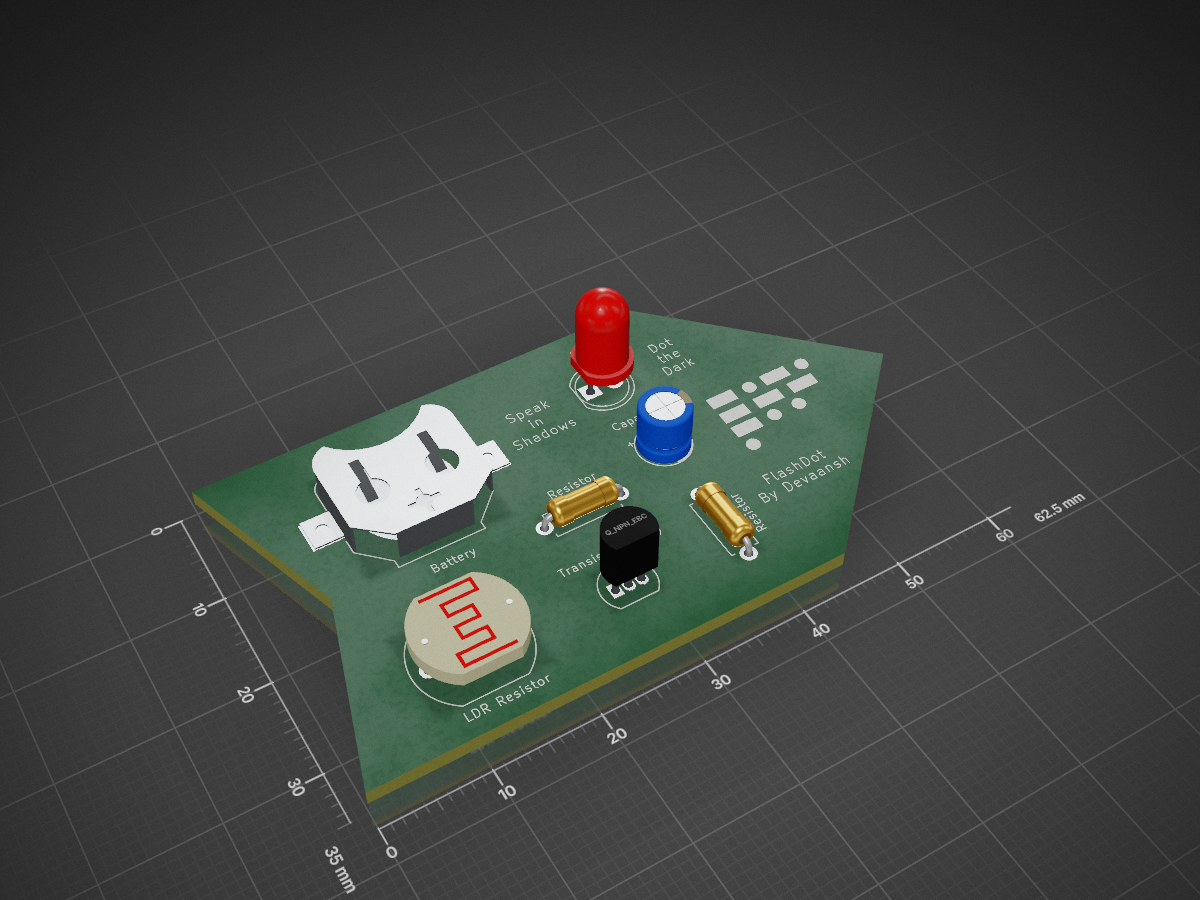
FlashDot is an open-source printed circuit board by DevaanshPathak, from the DevaanshPathak/FlashDot repository on GitHub, published under the MIT licence. It is a 2-layer board of 62.5 × 35 mm with 7 parts on 5 nets.
Its parts include 3 resistors, 1 capacitor, 1 diode and 1 transistor.
FlashDot is a simple analog circuit that lets you transmit Morse code using your hand and light. Wave your fingers over an LDR (photoresistor), and an LED blinks in response. It's tactile, visual, and powered by nothing but a transistor and your creativity.
This project was built for Hack Club’s Solder Program!
FlashDot reacts to light changes — when you cover the photoresistor, it flips on an NPN transistor, causing the LED to light up. With a single finger, you can tap out Morse code, send signals, or just vibe with light.
You can replace the LED with a vibration motor to make a tactile flasher too.
| Component | Quantity | Notes |
|---|---|---|
| Photoresistor (LDR - GL5528) | 1 | Senses ambient light |
| 2N3904 NPN Transistor | 1 | Main switch |
| 220Ω Resistor | 1 | LED current limiting |
| 47kΩ Resistor | 1 | Forms voltage divider with LDR |
| 10µF Electrolytic Capacitor | 1 | Debounces fast flickers |
| 5mm LED | 1 | Light output |
| CR2032 Coin Cell + Holder | 1 | Power source |
| PCB / Breadboard | 1 | Custom-designed PCB |


All files live in the
kicad/andgerbers/folders.
flashdot/
├── kicad/         → KiCad project, schematic, PCB layout
├── gerbers/       → Gerber + drill files (for fabrication)
├── imgs/          → Screenshots: schematic, PCB, 3D views
├── LICENSE        → MIT
└── README.md → You’re here!Power the circuit using a coin cell.
Then:
Devaansh Pathak
U091678RUNB
I wanted to make something dead simple, no microcontroller, no code — just light, your hand, and physics. FlashDot is my second analog PCB and my second time using KiCad. I learned about debounce circuits, transistor switching, and footprint alignment.
MIT — remix, learn, and solder your own.
Built for Hack Club Solder 💚
| Qty | Value | Footprint | References |
|---|---|---|---|
| 2 | R | Resistor_THT:R_Axial_DIN0207_L6.3mm_D2.5mm_P7.62mm_Horizontal | R1, R2 |
| 1 | Battery | Battery:BatteryHolder_Keystone_3000_1x12mm | BT1 |
| 1 | C_Polarized | Capacitor_THT:CP_Radial_D5.0mm_P2.00mm | C1 |
| 1 | LDR03 | OptoDevice:R_LDR_10x8.5mm_P7.6mm_Vertical | R3 |
| 1 | LED | LED_THT:LED_D5.0mm | D1 |
| 1 | Q_NPN_EBC | Package_TO_SOT_THT:TO-92_Inline | Q2 |
It measures 62.5 × 35 mm and has 2 copper layers, 1.6 mm thick.
7 parts. The full list of its parts is on this page, with links to each part's symbol and footprint where PCBKit's library has them.
From the DevaanshPathak/FlashDot repository on GitHub, at the commit this page was made from: the board is kicad/FlashDot.kicad_pcb and its schematic kicad/FlashDot.kicad_sch. PCBKit opens the board in the browser, with nothing to install.
Its repository publishes it under the MIT licence: you may reuse it on that licence's terms (keep the author's notice, and for a copyleft licence share your changes alike).
byrantech/laptop
anyon_e, a highly integrated, high end, open source laptop. Attempt the impossible.


AxxAxx/AxxSolder
STM32 Based soldering station for JBC cartridges, 9-24 VDC and USB-PD power


jamro/tiny-engineer
A small desktop robot that brings an AI coding assistant to life, physically acting out when it reads files, thinks, writes code, and finishes work.

hoglet67/RGBtoHDMI
Bare-metal Raspberry Pi project that provides pixel-perfect sampling of Retro Computer RGB/YUV video and conversion to HDMI
