

2 layers70.1 × 43.2 mm
Iaq device
nkitanov/iaq_board
IAQ Board is a DIY (Do-It-Yourself) device for measuring internal air quality
19 parts396

 deuteros76/co2-detector9
After reading this article (ES) I started to think about creating my own sensor board. I searched which sensor to use and the SGP30 seemed a good option to me.
Co2-detector is an open-source printed circuit board by deuteros76, from the deuteros76/co2-detector repository on GitHub. It is a 2-layer board of 37.5 × 51.4 mm with 13 parts on 20 nets, routed with 66 tracks and 0 vias.
It is built around the WEMOS D1 MINI and SGP30. Its parts include 4 resistors and 2 ICs. It belongs with the sensors and measurement and home automation and IoT boards and the ESP8266 boards of this library.
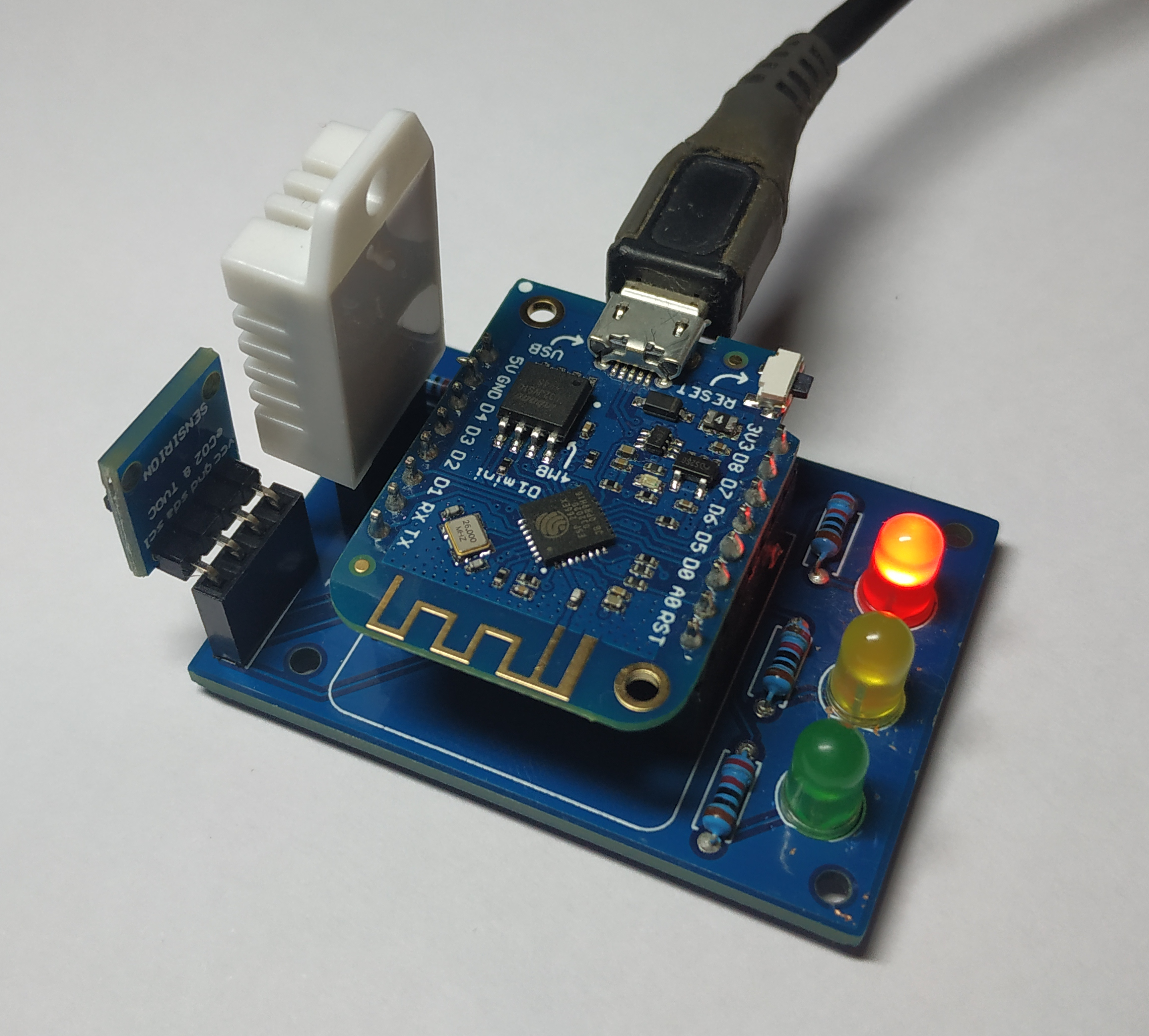
After reading this article (ES) I started to think about creating my own sensor board. I searched which sensor to use and the SGP30 seemed a good option to me. After a few tests, I modified the code of another project and then I built two prototypes which are currently working in my house. The device uses a mqtt queue to send data to an IoT gateway (a minipc running Home Assistant in my case). In addition to that, there are three LEDs to show what is the current state of the air based on CO2 PPMs:
You will find the hardware schematics and design files in the board directory. The hardware is distributed under the Cern Open Source Hardware License 1.2.
The software is available unde Apache 2.0 license and can be found in the co2-detector directory.
Documents found in this project are distrubuted under Creative Commons CC0 license.
During the first execution, the device will launch a WiFi access point. Using your PC or mobile device, check the available networks and connect to the network whose name starts with "CO2-detector". After that, point your browser to http://192.168.4.1 and the configuration page will be displayed.
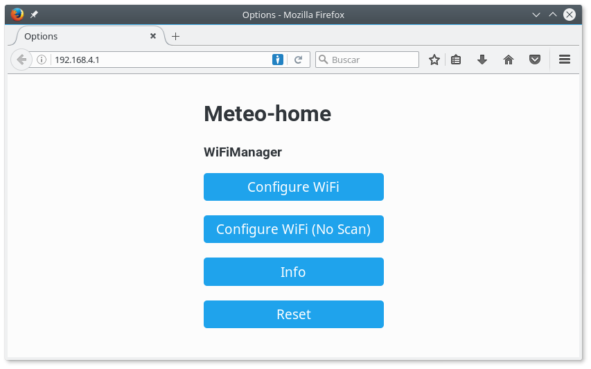
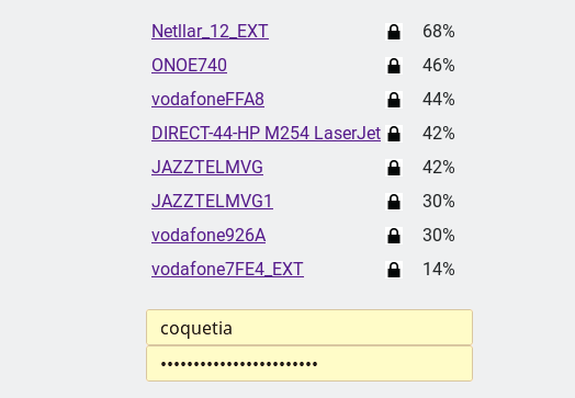
Choose the first option ("Configure WiFi") and select your WiFi network from the list of detected access points then, write your WiFi password. If your wifi network is open, leave the password field empty.
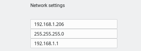
Now configure you network settings.
The device will publish all sensor data through mqtt so, the information is sent to another machine such as a minipc used as an IoT gatway. To do that, you have to introduce the data of the mqtt server.
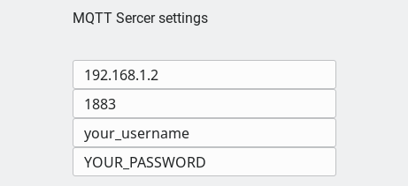
Then, fill all the fields related to your MQTT topic names and save your configuration. If you have several devices in different places you can change the prefix (room1/Temperature, room2/Temperature and so on).
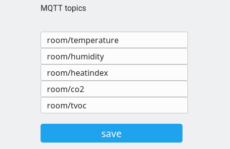
After saving the settings the device will be reset and then it will run in its normal mode, gathering data from all sensors.
All LEDs will be turned on when the device starts. After configuring the device, it will try to connect to the configured network. After that, only one LED will be lighted.
The CO2 sensor takes a measurement every second and sends an average of the last 60 CO2 and TVOC values every minute. The temperature and humidity sensor is used to correct the obtained data as explained in the SGP30 data sheet.
Device's LEDs are also useful to know the current state in case of error:
DHT22 (humidity and temperature sensor) errors are detected but not reported through the LEDs as this sensor is used to improve the accuracy of the CO2 readings but it is not critical if it doesn't work. It is possible to detect a malfunction in the DHT22 finding the last temperature and humidity readings in Homa Assistant (for instance if both values are not updated for many hours).
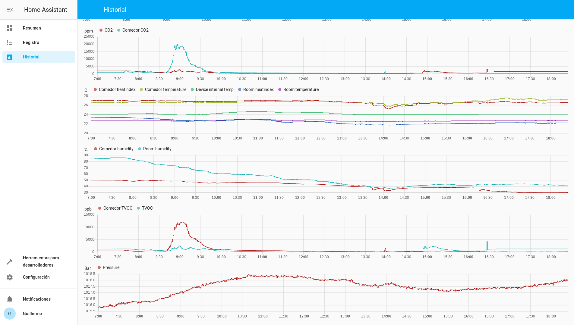
I use Home Assistant to collect all the data and display the information. The software runs in a miniPC (a SolidRun CuBox-i) which is a small home IoT server and also has the Mosquitto mqtt broker. The device sends sensors data to the mqtt broker and Home Assistant reads it and stores everything in a data base. In addition to that Home Assistant has a frontend application that shows the current status of all your sensors and historical graphs of a selected day. You can use any other similar software with the capability of subscribing to read from mqtt.
| Reference | Value | Footprint | Datasheet |
|---|---|---|---|
| D1 | Red | LEDs:LED_D5.0mm | |
| R3 | 90 | Resistors_THT:R_Axial_DIN0207_L6.3mm_D2.5mm_P7.62mm_Horizontal | |
| R4 | 10K | Resistors_THT:R_Axial_DIN0207_L6.3mm_D2.5mm_P7.62mm_Horizontal | |
| TH1 | DHT22_Temperature_Humidity | Sensors:DHT22_Temperature_Humidity | |
| U2 | SGP30 | Pin_Headers:Pin_Header_Straight_1x04_Pitch2.54mm | |
| D2 | Yellow | LEDs:LED_D5.0mm | |
| D3 | Green | LEDs:LED_D5.0mm | |
| R1 | 160 | Resistors_THT:R_Axial_DIN0207_L6.3mm_D2.5mm_P7.62mm_Horizontal | |
| R2 | 160 | Resistors_THT:R_Axial_DIN0207_L6.3mm_D2.5mm_P7.62mm_Horizontal | |
| U1 | WeMos_D1_mini | wemos-d1-mini:wemos-d1-mini-with-pin-header |
The following Home Assistant configuration file is an example of two CO2 detectors placed at different rooms within a house. One is in a dinner room while the second is monitoring a sleeping room. Each device sends the data provided by the SGP20 (CO2 and TVOC) and DHT22 (temperature, humidity and heat index) sensors to a mqtt queue which is installed in the computer hosting Home Assistant.
homeassistant:
  # Name of the location where Home Assistant is running
  name: Home
  # Impacts weather/sunrise data
  elevation: 50
  # C for Celsius, F for Fahrenheit
  temperature_unit: C
  # 'metric' for the metric system, 'imperial' for the imperial system
  unit_system: metric
  # Pick yours from here: http://en.wikipedia.org/wiki/List_of_tz_database_time_zones
  time_zone: Europe/Madrid

# Show links to resources in log and frontend
#introduction:

system_health:


group:
  kids:
    name: Kids room
    entities:
      - sensor.kids_temperature
- sensor.kids_humidity| Qty | Value | Footprint | References |
|---|---|---|---|
| 2 | 160 | Resistors_THT:R_Axial_DIN0207_L6.3mm_D2.5mm_P7.62mm_Horizontal | R1, R2 |
| 1 | 10K | Resistors_THT:R_Axial_DIN0207_L6.3mm_D2.5mm_P7.62mm_Horizontal | R4 |
| 1 | 90 | Resistors_THT:R_Axial_DIN0207_L6.3mm_D2.5mm_P7.62mm_Horizontal | R3 |
| 1 | DHT22_Temperature_Humidity | Sensors:DHT22_Temperature_Humidity | DHT22 |
| 1 | Green | LEDs:LED_D5.0mm | G |
| 1 | Red | LEDs:LED_D5.0mm | R |
| 1 | SGP30 | Pin_Headers:Pin_Header_Straight_1x04_Pitch2.54mm | U2 |
| 1 | WeMos_D1_mini | wemos-d1-mini:wemos-d1-mini-with-pin-header | U1 |
| 1 | Yellow | LEDs:LED_D5.0mm | Y |
The 10 most common of 13 parts.
nkitanov/iaq_board
IAQ Board is a DIY (Do-It-Yourself) device for measuring internal air quality


BHDynamics/dynossat-edu-obc
DynOSSAT-EDU, educational PocketQube satellite On-Board Computer files


vrubel/indicator-fun-V3s
"indicator.fun" device implementation on the processor Allwinner V3s

entropia/Teebeutel-Hardware
Teebeutel (eng. Teabag) is an electronic, Entropia themed con-badge for the GPN20, featuring an ESP32 microprocessor running micropython.


dustpot/indoor-air-monitor
A battery-powered ESP32 monitor for the non-particulate qualities of indoor air: temperature, humidity, pressure, eCO₂, and TVOC.
It measures 37.5 × 51.4 mm and has 2 copper layers, 1.6 mm thick.
13 parts, built around the WEMOS D1 MINI and SGP30. The full list of its parts is on this page, with links to each part's symbol and footprint where PCBKit's library has them.
From the deuteros76/co2-detector repository on GitHub, at the commit this page was made from: the board is board/co2-detector.kicad_pcb. PCBKit opens the board in the browser, with nothing to install.
Its repository states no licence, so its author keeps all rights: ask deuteros76 before reusing the design.