2 layers53.3 × 130.8 mm
 Desval27/Gateometry
Gateometry is an Arduino-based, 8-channel Euclidean rhythm generator for Eurorack synthesizers, featuring programmable rhythms, individual gate outputs and mute switches, external clock synchronization, and an OLED display with rotary encoder control for creating complex polyrhythms and evolving rhythmic patterns.
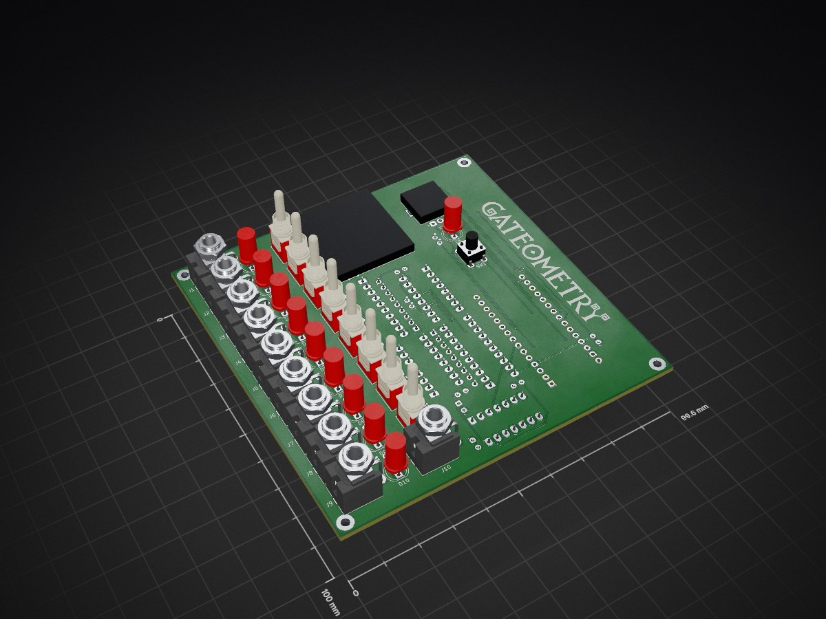
Gateometry is an open-source printed circuit board by Desval27, from the Desval27/Gateometry repository on GitHub, published under the MIT licence. It is a 2-layer board of 99.6 × 100 mm with 79 parts on 123 nets, routed with 517 tracks and 15 vias.
It is built around the 74HCT541D, 74HC165D and 74HC595, with the 74HCT14D and BAT85 among its other parts. Its parts include 24 resistors, 12 diodes, 11 connectors, 9 switches and 7 capacitors. It belongs with the audio and music and lEDs and displays boards and the AVR (ATmega, ATtiny) boards of this library.


!Untested!
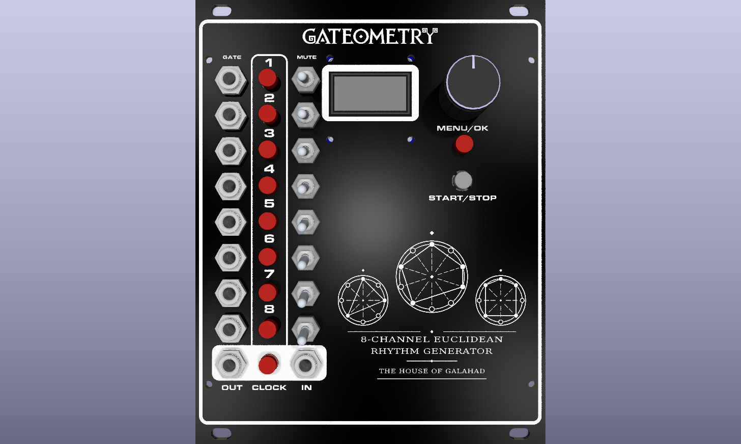
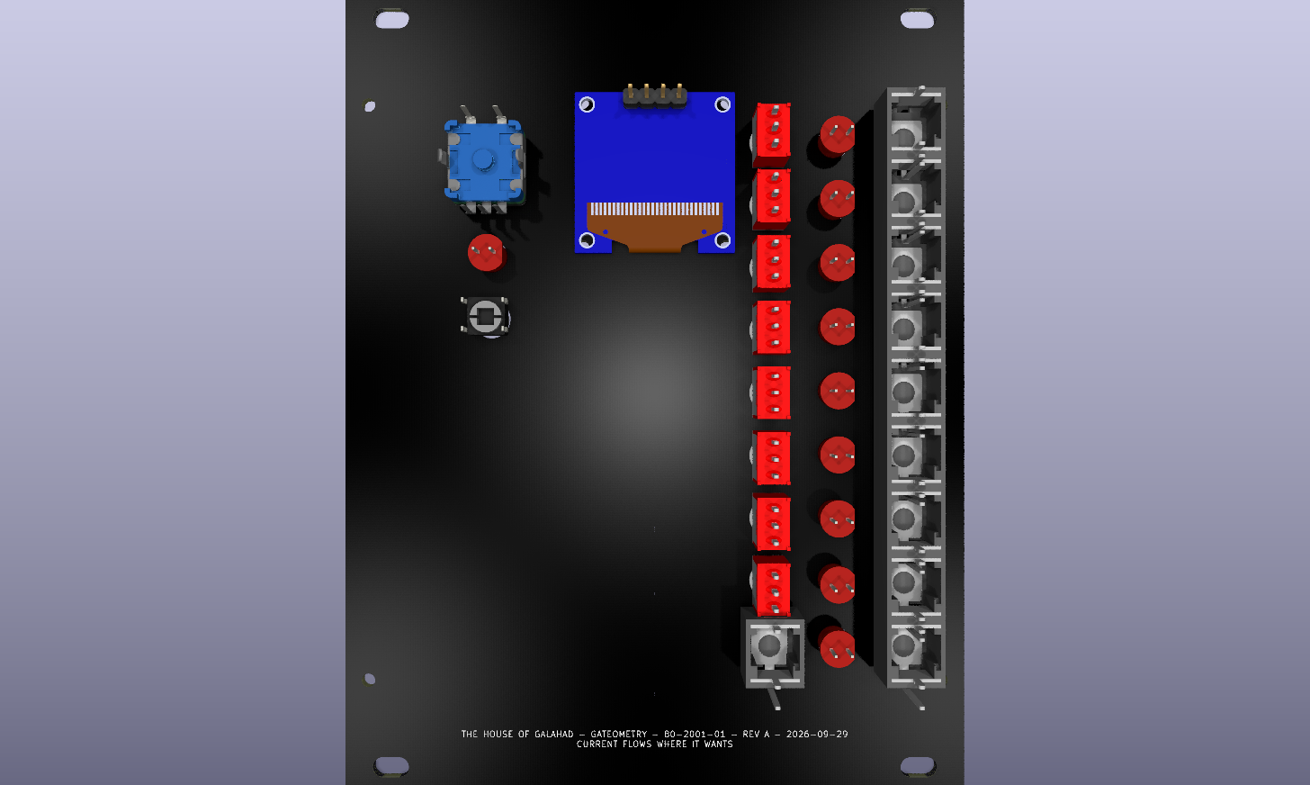
The Gateometry front panel provides a compact (for a given value of compact), intuitive interface for the eight-channel Euclidean rhythm generator. It features an OLED display for pattern visualization and menu navigation, a rotary encoder with an integrated pushbutton for parameter selection and editing, and dedicated run/stop and mute controls with LED status indication. Eight individual gate output jacks provide connections to external Eurorack modules, while clock input, clock output, and reset connections allow integration with other sequencers and clock sources. The panel is designed to provide convenient access to Gateometry's rhythmic capabilities while maintaining a clean, functional Eurorack layout.
| Qty | Value | Footprint | References |
|---|---|---|---|
| 9 | 1k | Resistor_THT:R_Axial_DIN0207_L6.3mm_D2.5mm_P2.54mm_Vertical | R1, R3, R4, R7, R11, R15, R16, R19, R20 |
| 9 | 4k7 | Resistor_THT:R_Axial_DIN0207_L6.3mm_D2.5mm_P2.54mm_Vertical | R2, R5, R6, R12, R13, R17, R18, R21, R22 |
| 6 | 100n | Capacitor_THT:C_Disc_D3.0mm_W1.6mm_P2.50mm | C2, C3, C4, C5, C6, C7 |
| 4 | MountingHole_Pad | MountingHole:MountingHole_2.2mm_M2_Pad_TopBottom | H1, H2, H3, H4 |
| 3 | 10k | Resistor_THT:R_Axial_DIN0207_L6.3mm_D2.5mm_P2.54mm_Vertical | R8, R9, R10 |
| 2 | 100k | Resistor_THT:R_Array_SIP9 | RN1, RN2 |
| 2 | 74HCT541 | Package_DIP:DIP-20_W7.62mm_LongPads | U2, U4 |
| 2 | BAT85 | Diode_THT:D_DO-35_SOD27_P7.62mm_Horizontal | D11, D12 |
| 1 | 0.96 Inch OLED I2C Display Module | Desval27:0.96 Inch OLED I2C Display Module | U3 |
| 1 | 100k | Resistor_THT:R_Axial_DIN0207_L6.3mm_D2.5mm_P2.54mm_Vertical | R24 |
| 1 | 10k | Resistor_THT:R_Array_SIP9 | RN3 |
| 1 | 22k | Resistor_THT:R_Axial_DIN0207_L6.3mm_D2.5mm_P2.54mm_Vertical | R23 |
| 1 | 2k2 | Resistor_THT:R_Axial_DIN0207_L6.3mm_D2.5mm_P2.54mm_Vertical | R14 |
| 1 | 47µ | Capacitor_THT:CP_Radial_D5.0mm_P2.00mm | C1 |
| 1 | 74HC165 | Package_DIP:DIP-16_W7.62mm_LongPads | U6 |
| 1 | 74HC595 | Package_DIP:DIP-16_W7.62mm_LongPads | U1 |
| 1 | 74HCT14 | Package_DIP:DIP-14_W7.62mm_LongPads | U5 |
| 1 | Arduino_Nano_v3.x | Desval27:MODULE_ARDUINO_NANO | A1 |
| 1 | CLOCK IN | Desval27:Jack_3.5mm_QingPu_WQP-PJ398SM_Vertical | J10 |
| 1 | CLOCK LED | LED_THT:LED_D5.0mm_FlatTop | D6 |
| 1 | CLOCK OUT | Desval27:Jack_3.5mm_QingPu_WQP-PJ398SM_Vertical | J9 |
| 1 | CLOCK OUT LED | LED_THT:LED_D5.0mm_FlatTop | D10 |
| 1 | GATE1 | Desval27:Jack_3.5mm_QingPu_WQP-PJ398SM_Vertical | J1 |
| 1 | GATE1 LED | LED_THT:LED_D5.0mm_FlatTop | D1 |
| 1 | GATE2 | Desval27:Jack_3.5mm_QingPu_WQP-PJ398SM_Vertical | J2 |
| 1 | GATE2 LED | LED_THT:LED_D5.0mm_FlatTop | D2 |
| 1 | GATE3 | Desval27:Jack_3.5mm_QingPu_WQP-PJ398SM_Vertical | J3 |
| 1 | GATE3 LED | LED_THT:LED_D5.0mm_FlatTop | D3 |
| 1 | GATE4 | Desval27:Jack_3.5mm_QingPu_WQP-PJ398SM_Vertical | J4 |
| 1 | GATE4 LED | LED_THT:LED_D5.0mm_FlatTop | D4 |
| 1 | GATE5 | Desval27:Jack_3.5mm_QingPu_WQP-PJ398SM_Vertical | J5 |
| 1 | GATE5 LED | LED_THT:LED_D5.0mm_FlatTop | D5 |
| 1 | GATE6 | Desval27:Jack_3.5mm_QingPu_WQP-PJ398SM_Vertical | J6 |
| 1 | GATE6 LED | LED_THT:LED_D5.0mm_FlatTop | D7 |
| 1 | GATE7 | Desval27:Jack_3.5mm_QingPu_WQP-PJ398SM_Vertical | J7 |
| 1 | GATE7 LED | LED_THT:LED_D5.0mm_FlatTop | D8 |
| 1 | GATE8 | Desval27:Jack_3.5mm_QingPu_WQP-PJ398SM_Vertical | J8 |
| 1 | GATE8 LED | LED_THT:LED_D5.0mm_FlatTop | D9 |
| 1 | MUTE1 | Desval27:2MS1T1B1M2QES | SW2 |
| 1 | MUTE2 | Desval27:2MS1T1B1M2QES | SW3 |
| 1 | MUTE3 | Desval27:2MS1T1B1M2QES | SW4 |
| 1 | MUTE4 | Desval27:2MS1T1B1M2QES | SW5 |
| 1 | MUTE5 | Desval27:2MS1T1B1M2QES | SW6 |
| 1 | MUTE6 | Desval27:2MS1T1B1M2QES | SW7 |
| 1 | MUTE7 | Desval27:2MS1T1B1M2QES | SW8 |
| 1 | MUTE8 | Desval27:2MS1T1B1M2QES | SW9 |
| 1 | OLED POWER | Connector_PinHeader_2.54mm:PinHeader_1x03_P2.54mm_Vertical | JP1 |
| 1 | POWER | Connector_IDC:IDC-Header_2x08_P2.54mm_Vertical | J11 |
| 1 | ROTARY ENCODER | Desval27:Rotary Encoder | ENC1 |
| 1 | RUN/STOP | Button_Switch_THT:SW_PUSH_6mm_H8mm | SW1 |
It measures 99.6 × 100 mm and has 2 copper layers, 1.6 mm thick.
79 parts, built around the 74HCT541D, 74HC165D, 74HC595 and 74HCT14D. The full list of its parts is on this page, with links to each part's symbol and footprint where PCBKit's library has them.
From the Desval27/Gateometry repository on GitHub, at the commit this page was made from: the board is hardware/Gateometry.kicad_pcb and its schematic hardware/Gateometry.kicad_sch. PCBKit opens the board in the browser, with nothing to install.
Its repository publishes it under the MIT licence: you may reuse it on that licence's terms (keep the author's notice, and for a copyleft licence share your changes alike).


FredericSegard/Fr80
Z80 Homebrew computer, code-named Fre80, pronounced Freddy.

MarkWestbroek/MusicBrain
A central brain running on teensy or a lighter MCU to process any control signals (MIDI, CV, our own) into the same but adding logic, ADSRs, DCOs, CV matrices etc. to it


aiabusalama/pumpbox
REISBOT Pump Guard: a Rust + Raspberry Pi box that keeps a 150 V solar water pump alive

tebl/BulkyMIDI-32
A HW build of the MT32-PI project, allowing you to emulate a Roland MT-32 using a Raspberry Pi. Includes enough additional modules to build a MIDI-mountain as well as adapters for connecting to most things retro.

alpyen/zynq-gbcartreader
Embedded Software Development project to read & write GameBoy cartridges.