2 layers198.1 × 95.3 mm

 denouche/led-o-clock13
This folder contains the KiCad design files, manufacturing data, and documentation for the Led'o'clock custom board.
Led o clock is an open-source printed circuit board by denouche, from the denouche/led-o-clock repository on GitHub. It is a 2-layer board of 49 × 35 mm with 24 parts on 25 nets, routed with 102 tracks and 21 vias.
It is built around the ESP32-C3-WROOM-02-H4 and AP7361C-33E. Its parts include 6 capacitors, 5 resistors, 2 ICs, 2 connectors and 2 switches. It belongs with the lEDs and displays boards and the ESP32 and RISC-V boards of this library.


🚧 WORK IN PROGRESS: The v3.2 PCB design is currently being finalized. Files and documentation may change frequently. This v3.2 version will not require any manual soldering, as all components (including the USB-C module) are now designed for SMD assembly by JLCPCB. The documentation below still applies to the previous v3.0 version which requires some manual soldering.
This folder contains the KiCad design files, manufacturing data, and documentation for the Led'o'clock custom board.
The board is built around the ESP32-C3 microcontroller. To optimize production costs, the surface-mount devices (SMD) are designed to be assembled by JLCPCB, but some manual soldering is required to complete the board.
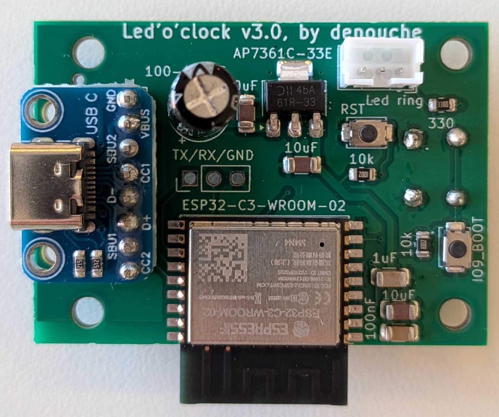
The PCB is designed for partial assembly (SMD only) using JLCPCB's "Basic" parts.
jlcpcb/production_files/GERBER-led-o-clock.zip.jlcpcb/production_files/BOM-led-o-clock.csv.jlcpcb/production_files/CPL-led-o-clock.csv.Note: Although the through-hole components listed below have footprints and LCSC part numbers in the KiCad project, they were intentionally excluded from the automated assembly files to minimize factory setup fees.
Here is the resulting board you should receive from the factory, with all SMD components pre-soldered:
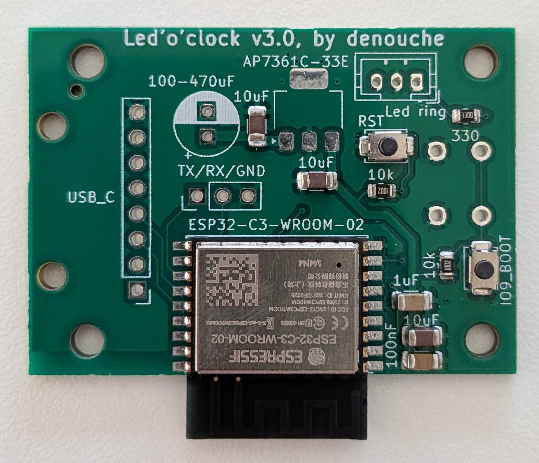
Once you receive the partially assembled boards from the factory, you must manually solder the following through-hole components:
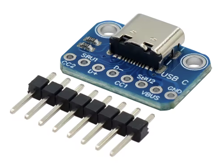
USB-C Module (6-pin): A standard 6-pin USB-C female breakout board. ⚠️ IMPORTANT: The module must feature two 5.1kΩ pull-down resistors on the CC1 and CC2 pins. Without these resistors, the device will NOT work with USB-C to USB-C cables or PD chargers.
JST PH 2.0 Connector (3-pin): A horizontal female connector to plug in the LED ring.
Capacitor: A 330µF electrolytic capacitor for power smoothing. (Pay attention to the polarity!)
Tactile Switch: A 6x6mm push button. Important: This component must be soldered on the BOTTOM side of the PCB so it aligns properly with the 3D printed enclosure hole.
| Qty | Value | Footprint | References |
|---|---|---|---|
| 3 | 10uF | Capacitor_SMD:C_1206_3216Metric | C2, C4, C6 |
| 2 | 10k | Resistor_SMD:R_0805_2012Metric | R2, R3 |
| 2 | 5.1k | Resistor_SMD:R_0805_2012Metric | R1, R5 |
| 2 | LOGO | LOGO | G***, G*** |
| 1 | 100nF | Capacitor_SMD:C_1206_3216Metric | C3 |
| 1 | 100uF | Capacitor_SMD:CP_Elec_6.3x5.4 | C11 |
| 1 | 1uF | Capacitor_SMD:C_1206_3216Metric | C5 |
| 1 | 330 | Resistor_SMD:R_0805_2012Metric | R4 |
| 1 | AP7361C-33E | Package_TO_SOT_SMD:SOT-223-3_TabPin2 | U1 |
| 1 | ESP32-C3-WROOM-02 | RF_Module:ESP32-C3-WROOM-02 | U2 |
| 1 | FerriteBead_Small | Inductor_SMD:L_0603_1608Metric | FB1 |
| 1 | IO9_BOOT | Button_Switch_SMD:SW_SPST_TS-1088-xR020 | SW3 |
| 1 | Led ring | Connector_JST:JST_PH_S3B-PH-K_1x03_P2.00mm_Horizontal | J4 |
| 1 | RST | Button_Switch_SMD:SW_SPST_TS-1088-xR020 | SW4 |
| 1 | USB_C_Receptacle_USB2.0_16P | Connector_USB:USB_C_Receptacle_HRO_TYPE-C-31-M-12 | J1 |
The 20 most common of 24 parts.
It measures 49 × 35 mm and has 2 copper layers, 1.6 mm thick.
24 parts, built around the ESP32-C3-WROOM-02-H4 and AP7361C-33E. The full list of its parts is on this page, with links to each part's symbol and footprint where PCBKit's library has them.
From the denouche/led-o-clock repository on GitHub, at the commit this page was made from: the board is pcb/led-o-clock.kicad_pcb and its schematic pcb/led-o-clock.kicad_sch. PCBKit opens the board in the browser, with nothing to install.
Its repository states no licence, so its author keeps all rights: ask denouche before reusing the design.

nodestark/mdb-esp32-cashless
ESP32-based MDB cashless device for vending machines, supporting EVA DTS DEX/DDCMP telemetry and payments over the MDB protocol via Bluetooth and MQTT

sabogalc/KiCad-Arduino-Boards
A collection of Arduino boards recreated from scratch in KiCad. Legacy USB connectors have been replaced with USB-C where applicable.

cbskii/storyboard-keyboard
5x12 split ortholinear keyboard with an E-INK display


wr/airwriter
Print to vintage Apple printers from modern devices over AirPrint, or from a vintage Mac over AppleTalk.